Installation
AFDH-SVN004C-EN 47
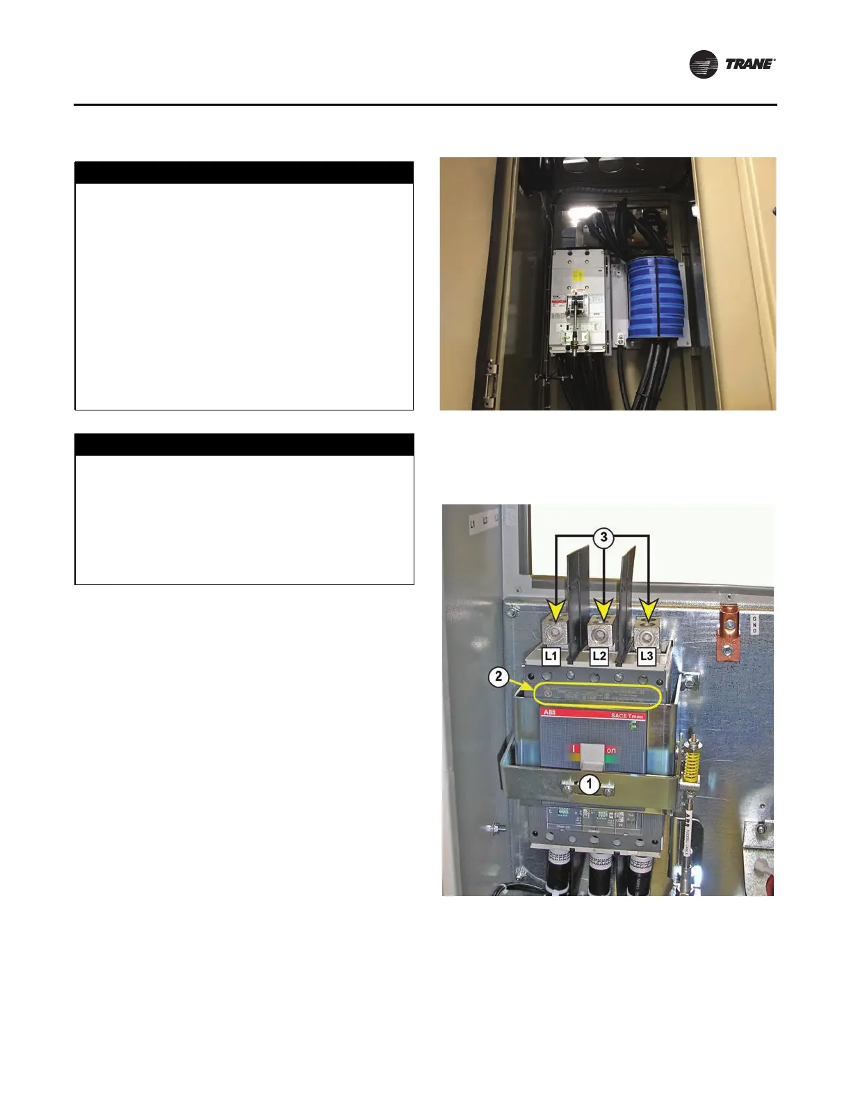
Input Power Wire Installation
Note: The L1, L2, and L3 input power leads for this unit
will be connected to a factory installed input
disconnect circuit breaker inside of the drive
cabinet.
1. To prevent metallic debris from falling into the drive,
remove
the access cover pieces and take them to
another location for marking and drilling the required
wire routing holes for the input wire leads.
Notes:
• These wire routing holes are the only entry points
that should be used for bringing input power wiring
into the drive cabinet.
• In
some cases, the top plate with conduit hubs from
the original starter may be reused and installed over
the incoming wire access cut-out on the top of the
cabinet, in place of the two-piece access covers.
a. Install the appropriate conduit hubs before
reinstalling
the access door pieces on top of the
cabinet.
2. Route the input wire leads into the cabinet and connect
them
to circuit breaker terminals L1, L2, and L3.
a. The torque specification for these terminal
connections
is 23 foot-pounds.
Note: Adjustable circuit breaker to accommodate inlet
wires length.
NOTICE
Route Incoming Power Conduit to the
Roof of the AFDH Cabinet!
Routing the incoming power conduit into the AFDH
cabinet anywhere other than through the specified
location on the cabinet roof, will be considered an
unsupported field modification to the cabinet design.
The air-cooled AFDH drive is designed to have the
incoming power conduit routed vertically into the unit
through the removable conduit connection cover
located on the left-hand rear corner of the cabinet roof.
If the starter that is being replaced by the AFDH drive
has the incoming power conduit routed horizontally
across the top of the starter, or connected to the side or
to the bottom of the starter cabinet, an electrician will
be required to reconfigure the conduit and wiring.
NOTICE
Keep Dirt, Debris, or Metal Filings From
Entering the Drive Cabinet!
Failure to observe the appropriate precautions could
result in damage to the electrical components when
they are energized for the first time. Take all precautions
necessary to prevent any dirt, debris, or metal filings
from entering into the drive cabinet during the
installation process.
Figure 38. Adjustable circuit breaker
Figure 39. Factory installed input disconnect circuit
breaker
1. Input disconnect circuit breaker
2. Nameplate
3. Input power terminals. Terminal connections should be torqued
to 23 foot·pounds