Installation
50 AFDH-SVN004C-EN
Important: If the chiller does not already have a
condenser pressure transducer. Do not
forget to install the condenser pressure
transducer provided in the Tracer®
AdaptiView™ Miscellaneous Hardware
Package. The accurate pressure readings
required by the chiller controls to enable the
most efficient operation of the chiller with
the upgraded AFDH drive can only be
effectively measured with a pressure
transducer.
Required Reprogramming of
Tracer® AdaptiView™ Controls.
Reprogramming Factory Installed Tracer®
AdaptiView™ Controls (CTV Simplex
Firmware)
Important: Make sure your laptop is loaded with the
most current version of Tracer TU tool
software so that you have the most up-to-
date version of CTV MP firmware available
to install into the UC800.
Note: CTV
MP firmware is always used in factory installed
Tracer® AdaptiView™ control systems or in
Tracer® AdaptiView™ display upgrades to factory
installed CH530 control systems.
1. Factory installed wiring
2. Field installed wiring
3.
Note: Actual wire designators may vary depending upon the specific model/version of chiller control that the AFDH drive is being linked with.
Please refer to the original chiller control wiring diagrams and the wire descriptions listed in Figure Callouts 4–11 if an actual wire designator
does not match the one shown in this graphic.
4. 115VAC feed to chiller control panel
5. Neutral feed to chiller control panel
6. Normally Closed terminal(2) on HPC (High Pressure Cutout) switch (3S1) for original chiller with starter module and/or non-comm. Drive
terminal 4 is 115VAC only.
Note: For original chillers with a communicating drive, high pressure cutout wiring is 24V. For original chillers with a starter module, high pressure cutout
wiring is 115V.
7. From 1A7 J2-4 oil pump LLID
8. From 1A7 J2-2 oil LLID or could come from the 1X1 terminal block
9. and 10. Normal closed terminal on HPC switch (3S1) for original chiller with comm. Drive terminals 9 and 10 are 24VDC only.
Note: For original chillers with a communicating drive, high pressure cutout wiring is 24V.
11. 12. and 13. From UC800 IMC Modbus link
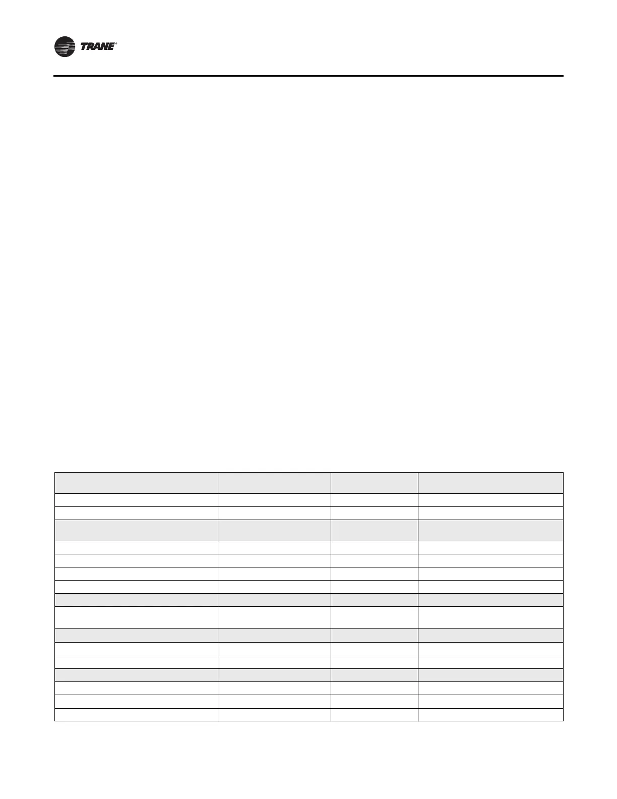
Table 26. UC800/Tracer® AdaptiView™ CTV parameter values with upgrade AFDH
Tracer TU Service Setpoints View:
Adjustable Frequency Drive Setpoints
Range Default Setting Recommended Setting
AF Control Auto, Fixed Auto Auto
ReOptimization Sensitivity 0–100% 20 20
Tracer TU Field Startup View:
Adjustable Frequency Drive
Range Default Setting Recommended Setting
AFD Temperature Limit Setpoint 0.0 - 360.0 212.0 212.0
Maximum Frequency 30–60 Hz 60 60
Minimum Frequency 30–60 Hz 38 38
Surge Speed Increase 0–2 Hz 1 1
Tracer TU Configuration View: Main Range Default Setting Recommended Setting
Unit Type (MODL) CVHE, CVHF, CVHG, CVGF CVHE
Enter Chiller Model from Unit Nameplate
(Note: only CVHE or CVHF apply)
Tracer TU Configuration View: UC800
Range Default Setting Recommended Setting
Starter Type Not Applicable Unit Mount Wye-Delta TR200 Modbus AFD
Impeller Diameter (CPIM) 50-345 275 Enter CPIM from Unit Nameplate
Tracer TU Configuration View: Starter Range Default Setting Recommended Setting
Unit Line Voltage 180–15000V 460 Enter from Unit Nameplate
Motor NP Power 4000 kW 400 Enter from Unit Nameplate
Motor Temperature Protection Type 75 Ohm@75F, 100 Ohm@ 0C 75 ohm 75 ohm