Installation
AFDH-SVN004C-EN 43
Linkage Bracket Installation for a
Unit- Mounted Direct Mount E-
Frame
1. Install drive on direct mount stand. Loosely attach
bolts to motor flange. Tightly attach bolts to base.
Leave lifting gantry connected to right side of AFD.
2. Install linkage bar to mounting handle with bolt,
washers
and nut, but do not fasten the bolts. Because
linkage bar need to be adjusted to a proper direction
when install into tube sheet.
3. Install linkage subassembly into tube sheet with bolt,
spacers, plane washer and nut. Ensure bolt is
tightened to 150 ft-lbs torque.
WARNING
Heavy Objects!
Failure to follow instructions below or properly lift unit
could result in unit dropping and possibly crushing
operator/technician which could result in death or
serious injury, and equipment or property-only damage.
Ensure that all the lifting equipment used is properly
rated for the weight of the unit being lifted. Each of the
cables (chains or slings), hooks, and shackles used to
lift the unit must be capable of supporting the entire
weight of the unit. Lifting cables (chains or slings) may
not be of the same length. Adjust as necessary for even
unit lift.
WARNING
Improper Unit Lift!
Failure to properly lift unit could result in unit dropping
and possibly crushing operator/technician which could
result in death or serious injury, and equipment or
property-only damage. An AFDH cabinet assembly is
top heavy. Test lift unit approximately 24 inches to
verify proper center of gravity lift point. To avoid
dropping of unit, reposition lifting point if unit is not
level.
WARNING
Unit Lowering!
Do not drop the drive cabinet assembly onto the
evaporator mounting brackets when setting it into
position! Dropping the cabinet onto the brackets could
result in damage to the drive cabinet, the brackets, and/
or the evaporator shell.
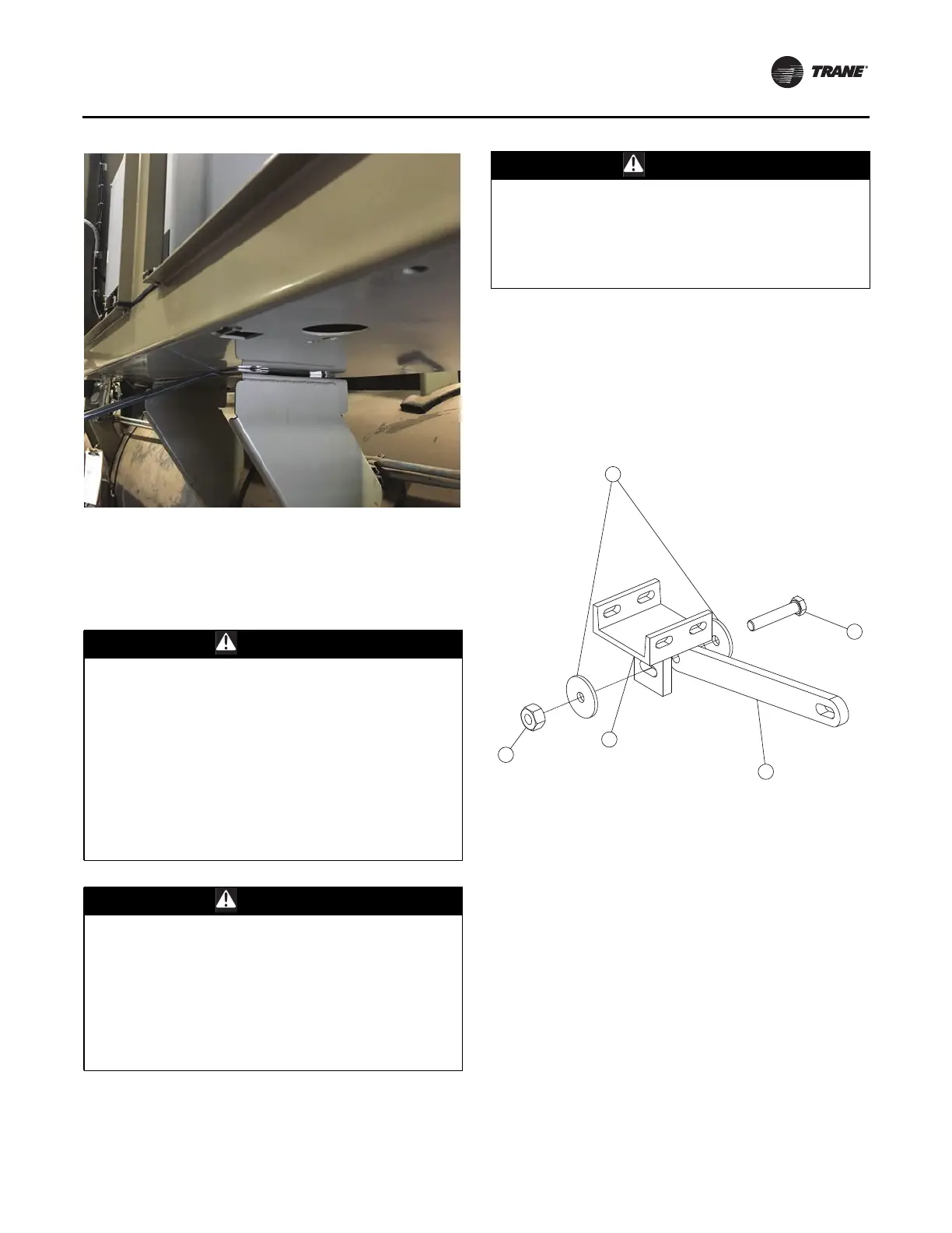
Figure 32. Linkage subassembly installation
1
2
3
4
5
1. Mounting Handle
2. Linkage bar
3. Bolt
4. Washer
5. Nut