AFDH Startup Procedure
52 AFDH-SVN004C-EN
TR200 Drive Configuration
Note: Technician may elect to configure the drive by
using Danfoss VLT Motion Control tool MCT10.
Follow the following steps:
1. If the TDU Drive Utility Program is installed on your
laptop:
You must first uninstall the TDU Drive Utility in
order to install the MCT 10 software.
2. Install MCT 10 toll: HUB Document DOC-155220: MCT
10
Installation Instructions.docx (Danfoss VLT Motion
Control Tools MCT 10 Set-up Software manual)
3. Configure the TR200 drive using MCT 10 tool: HUB
Document
DOC-179427: Creating a Project a Master
File and Configuration for AFDH D & E-Frame
Drive.docx (AFDH D & E-Frame Drive Configuration
Instructions Using MCT 10 Tool).
To manually configuring the drive, you should ensure the
drive
is at the default sittings by performing the following
procedures to reset the drive:
1. Disconnect power to the drive, and wait for the display
to
shut down.
2. While powering up the drive, press and hold the
following
keys: Status, Main, and OK.
3. After 5 seconds, release the keys.
After the drive is reset, reprogram the items listed in the
below
tables.
After all settings are made save a copy chiller service
report for future use. Recommend that Trane Techs load to
ComfortSite by chiller serial number.
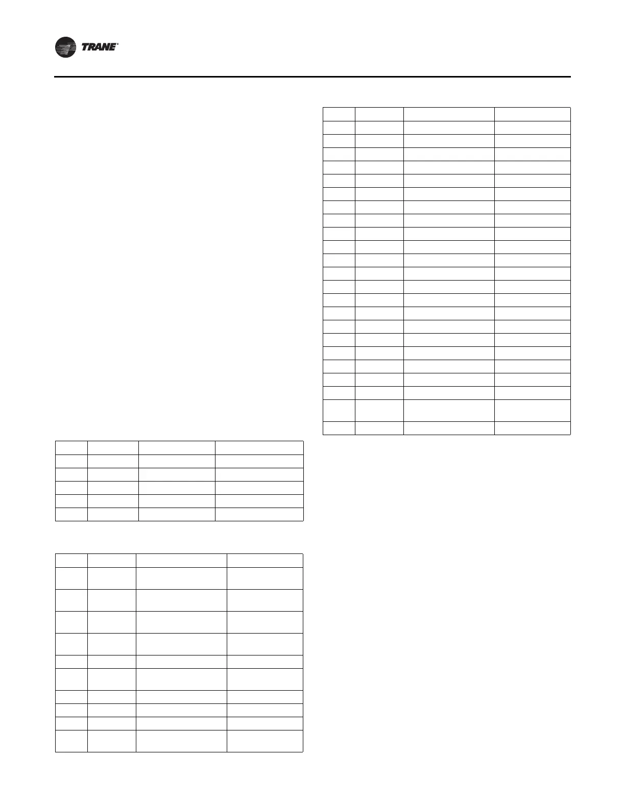
Table 27. Job specific settings
Group Parameter Description Value
1 20 Motor kW Set to nameplate NMKW
1 24 Motor Current Set to nameplate NMRA
1 25 Motor Nominal speed Set to nameplate TRPM
4 16 Torque limit mode Set to maximum
4 18 Current limit Set to maximum
Table 28. Trane default settings
Group Parameter Description Setting
0 20 Display line 1.1 small
DC link voltage
(1630)
0 21 Display line 1.2 small
Motor Current
(1614)
0 22 Display line 1.3 small
Heat sink temp
(1634)
0 23 Display line 2 large
Input Power Kw
(1610)
0 24 Display line 3 large Freq Hz (1613)
032
Custom Readout Max
Value
Nameplate NMRA
0 40 Hand on key Disabled (0)
0 41 Off key Disabled (0)
0 60 Main Menu password 999
061
Access to main menu w/
o password
LCP; Read only (1)
1 03 Torque characteristics Variable torque (1)
1 22 Motor voltage Nameplate voltage
1 23 Motor frequency 60 Hz
1 39 Motor poles Poles (2)
3 02 Minimum Reference 30 Hz
3 03 Maximum Reference 60 Hz
3 15 Reference 1 Source No Function
3 16 Reference 2 Source No Function
3 41 Ramp 1 ramp up time 10 sec
3 42 Ramp 2 ramp down time 20 sec
4 12 Motor speed low limit 38 Hz
4 14 Motor speed high limit 60 Hz
5 12 Terminal 27 Digital Input No operation (0)
5 40.1 Function Relay Running
8 01 Control Site Controlword only (2)
8 03 Control Timeout Time 15 sec
8 04 Control Timeout Function Stop
8 30 Protocol Modbus RTU
8 31 Address 3
8 32 Baud Rate 38400 Baud
8 33 Parity / Stop Bits No Parity, 1 Stop Bit
836
Maximum Response
Delay
100
14 21 Automatic Restart Time 10 sec
Table 28. Trane default settings (continued)
Group Parameter Description Setting