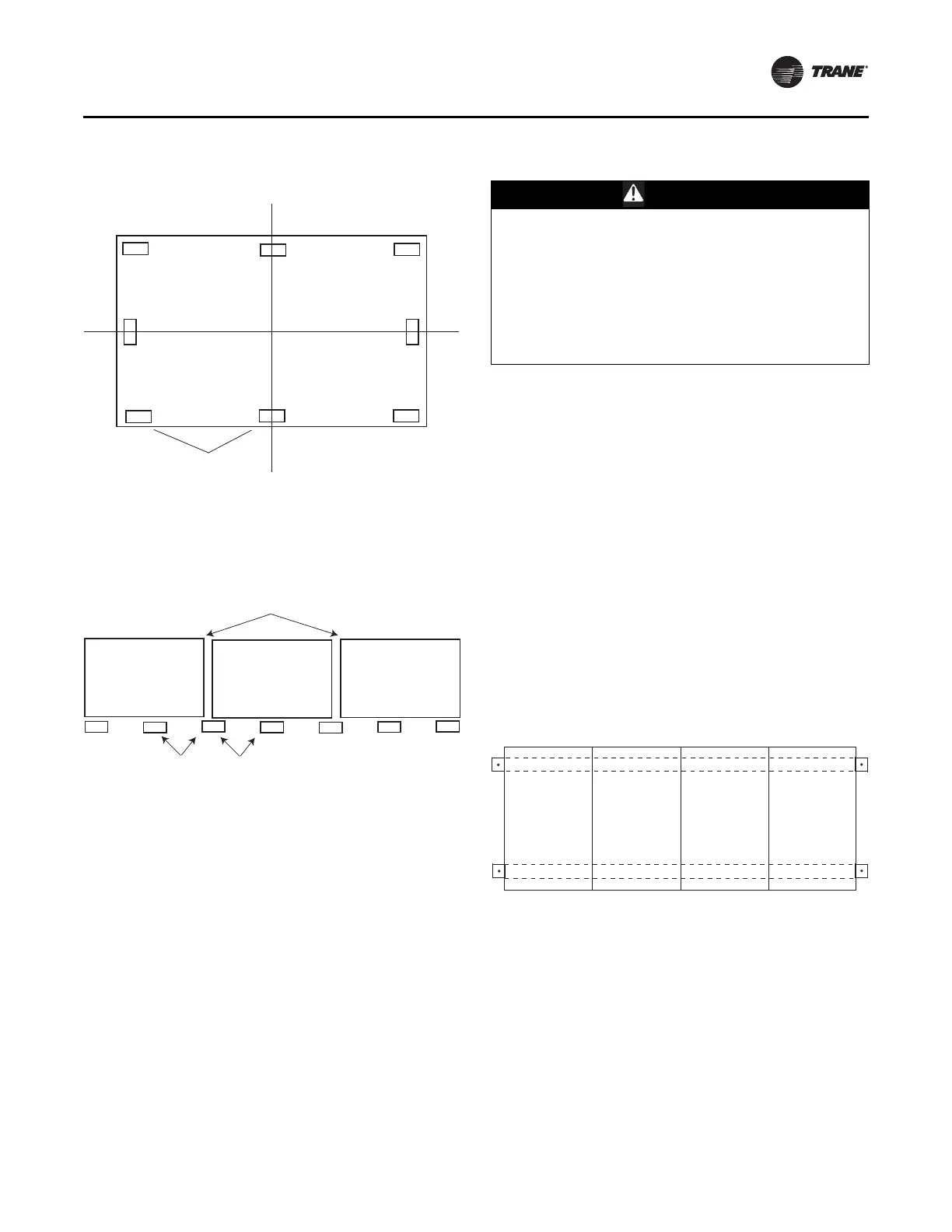
Figure 10. Piers located in each corner and spaced evenly
every four feet
Note: Piers beneath shipping splits must be structurally
sound
to support the weight of the unit.
Figure 11. Side view with two shipping splits - locate
one pier directly under each shipping split
Note: Piers beneath shipping splits must be structurally
sound
to support the weight of the unit.
Installation - Mechanical
CLCH-SVX013B-EN 17
For proper operation, the unit must be installed level (zero
tolerance) in both horizontal axes. For vertical discharge
units, allow space under the unit for supply air ductwork
connections.
Note: Ai
r handlers often include optional factory-
provided casing penetration entry points for field-
provided wiring. Consider overall unit
serviceability and accessibility before mounting,
running wires (power), making cabinet
penetrations, or mounting any components to the
cabinet.
See “Component Installation,” p. 36 for special assembly/
in
stallation considerations.
Removing the Shipping Skid
Remove the wooden shipping blocks, wooden toe cleat if
there is one, and end cleats prior to lowering unit into final
position or installing the unit to the roof curb.
Ceiling Suspension
WARNING
Risk of Unit Dropping!
Do not use mounting legs for ceiling suspension,
external isolation, or unit support during module
placement. Mounting legs are designed only to secure
the unit to the floor, housekeeping pad, or platform.
Improper use of the mounting legs as described above
could result in unit dropping and crushing technicians
which could result in death or serious injury, and
equipment damage.
Note: Cei
ling suspension is not recommended for units
larger
than 28,000 CFM unless using a field-
provided mounting frame.
Using a Field-Provided Mounting Frame
If a field-provided mounting frame is used for ceiling
suspension, the installer/contractor must provide a
ceiling-suspended mounting frame designed to support
the length, width, and weight of the entire air-handling
unit. See “Dimensions and Weights,” p. 12 for
approxim
ate weights.
Note: It is the building engineer’s responsibility to size the
structural
channels and to provide the appropriate
hangers.
Structural channels in a field-pr
ovided fram
e can be
mounted parallel to airflow or perpendicular to airflow:
• For parallel-to-airflow channels, size channels based
on a four-poi
nt load distribution (see Figure 12.
Figure 12. Typical suspension method-parallel channels
• For perpendicular-to-airflow channels, size channels
based on the load distribution of the individual
sections and install the channels so that both ends of
every section are supported (see Figure 13).
4 feet
Shipping split
4 feet