56 CLCH-SVX013B-EN
Installation - Electrical
WARNING
Hazardous Voltage w/Capacitors!
Disconnect all electric power, including remote
disconnects and discharge all motor start/run
capacitors before servicing. Follow proper lockout/
tagout procedures to ensure the power cannot be
inadvertently energized. For variable frequency drives
or other energy storing components provided by Trane
or others, refer to the appropriate manufacturer’s
literature for allowable waiting periods for discharge of
capacitors. Verify with an appropriate voltmeter that all
capacitors have discharged. Failure to disconnect
power and discharge capacitors before servicing could
result in death or serious injury.
For additional information regarding the safe discharge
of capacitors,
see PROD-SVB06A-EN
.
NOTICE
Use Copper Conductors Only!
Unit terminals are not designed to accept other types
of conductors. Failure to use copper conductors could
result in equipment damage.
Note: Ai
r handlers often include optional factory-
provided casing penetration entry points for field-
provided wiring. Consider overall unit
serviceability and accessibility before mounting,
running wires (power), making cabinet
penetrations, or mounting any components to the
cabinet.
Units intended for indoor use ar
e available with variable-
frequency drives (VFDs) that are externally mounted in an
enclosure or internally mounted in a recessed cabinet.
Units intended for outdoor use are only available with
internally mounted VFDs. A typical internally mounted
VFD is shown in Figure 73.
Figure 73. Internally mounted VFD
A typical externally mounted VFD is shown in Figure 74.
Figure 74. Externally mounted VFD
A typical wiring schematic for a VFD is shown in Figure 80.
Unit specific wiring schematics are shipped with each unit.
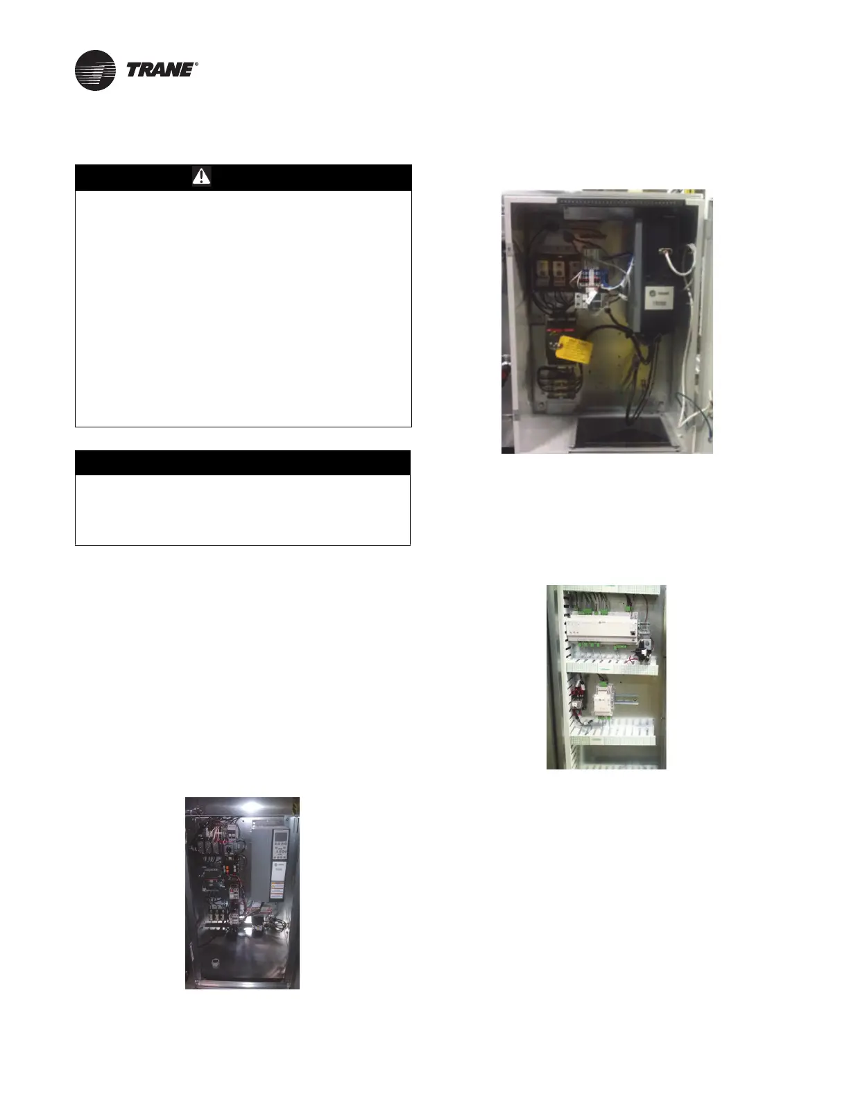
All units with VFDs that have direct-digital controlle
rs
(DDCs) are provided with line voltage to 24 Vac power
transformers as shown in Figure 75.
Figure 75. Controller - internally mounted
When provided, the line voltage to 24 Vac transformers are
factory wired to the supply fan power feed. All units with
factory-mounted controllers, and no VFDs, are provided
with 120 Vac to 24 Vac control transformers, as shown in
Figure 76, and require a separate 120V field connection.