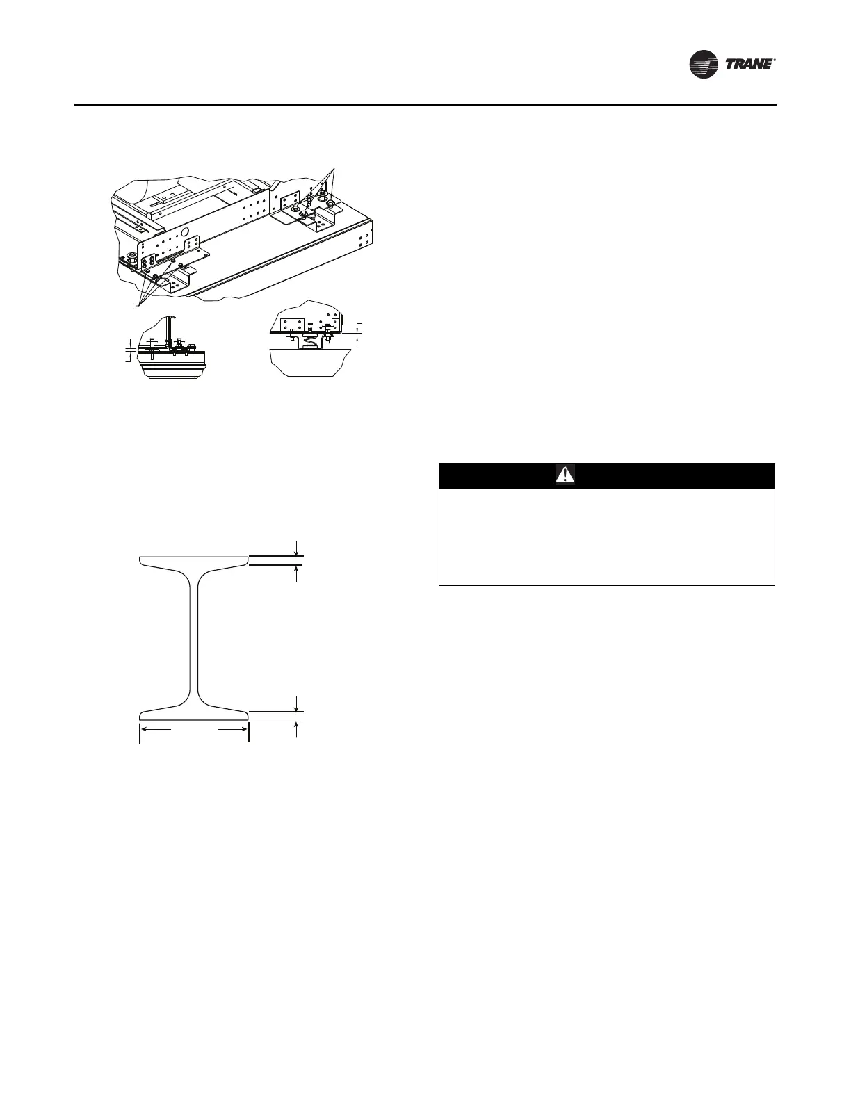
Figure 47. Tie-down removal
Tiedown
Tiedown
Clearance
Clearance
Component Installation
CLCH-SVX013B-EN 37
Motor Removal Rail
The motor removal rail provide is to be used for fan motor
removal and installation. The hoist is not provided by the
factory. For hoist selection, please refer to the rail cross
section provided in Figure 48. The maximum load for the
rail is 500 lbs (h
oist plus motor).
Figure 48. Motor removal rail
Filters
Bag and cartridge filter sections can be used as a pre-filter
section, a final filter section, or both. This use is
determined by the filter’s placement in relation to the fan.
• A final filter is placed after the fan.
• A pre-filter is placed before the fan.
Note: Cartridge and bag filter
s provided by Tr
ane are
fitted with a 7/8-inch header that fits in the filter
track. If using filters supplied by another
manufacturer, filters should be purchased with a 7/
8-inch header. In some cases it may be necessary to
gasket other manufacturers’ filters to ensure a
good air seal.
Filters should be installed when the unit is set. This will
protect
internal components, such as the heating and
cooling coils.
Final Filter Section
A final filter section should not be bolted directly to the
face of a fan section. One or more intermediate sections
must be placed between the fan discharge and the filter
section.
Pre-Filter Section
A pre-filter section has no special installation
requirements unless placed directly upstream of a plenum
fan. In these configurations, ensure a blank section is
placed between the fan inlet and the filter section.
Trane recommends the use of disposable pre-filters with
high-
efficiency filters.
Disposable pre-filters slide into the
mounting tracks just ahead of the bag/cartridge filters.
Filter Installation
WARNING
Hazardous Voltage!
Disconnect all electric power, including remote
disconnects before servicing. Follow proper lockout/
tagout procedures to ensure the power can not be
inadvertently energized. Failure to disconnect power
before servicing could result in death or serious injury.
To install filters:
1. Disconnect the power to the unit.
2. Open the filter sect
ion access door.
3. Slide the filters into the tracks.
Note: Bag filt
ers must be installed with t
he pleats in the
vertical plane.
4. The block-off is permanently installed and will create a
seal when the access do
or is closed.
5. Close the access door slowly to allow
any gasketing to
compress.