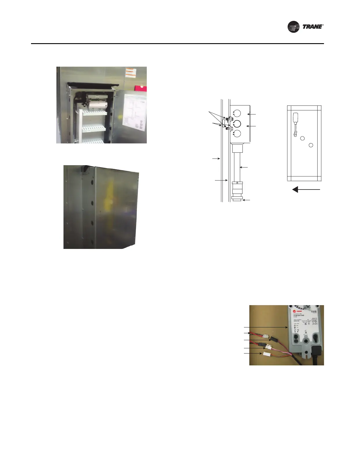
Figure 76. Controller - externally mounted
Figure 77. Externally mounted control box
Installation - Electrical
CLCH-SVX013B-EN 57
As with VFDs, units intended for indoor use are available
with DDCs mounted internally (see Figure 75) or externally
(seeFigure 76 and Figure 77), while units intended for
outdoor use are only available with
internally mounted
DDCs.
In units with 24Vac LED marine li
ghts, the l
ights are wired
together to a single switch located in the controls interface
module. Figure 77 shows a typical mounting of the
controls interface module with an externally mounted
controller. When DDCs are provided, the lighting circuit is
powered from the DDC power feed and does not require a
separate power source. When marine lights are provided
without DDCs, the lighting circuit requires a separate 120V
field connection that powers the lights through a 120V to
24Vac power transformer.
A mounted GFCI receptacle is provided for all units that
ha
ve DDCs or marin
e lights. The receptacle is mounted in
the controls interface module (see Figure 77) with the unit
light switch. The receptacle requires a separate 120V
power feed.
The electric heat door may ha
ve a solenoid locking
mechanism to pre
vent opening the control panel while the
electric heater is energized.
Field installed DDC control devices:
• Install outside-air sensor and space sensor, if ordered.
• Connect control valves, if ordered, to the valve jack
provid
ed as part of the unit wi
ring harness. The valve
jack is typically located at the air-leaving side of the coil
connection inside the casing panel. For valve junction
box mounting and wiring detail, see Figure 78.
Figure 78. Junction box for valve wiring
#10
self-drilling
screws (2)
2 x 4
junction box
Cover
Conduit
assembly
Valve
connection
End panel
Double-
wall panel
Bushing
(2 required
for units with
double-wall)
Airflow
Quick Connects
The actuators, factory-mounted or field-supplied, are
separately wired and controlled by a direct-digital
controller or other building logic. Figure 79 illustrates the
typical quick connect scheme.
Note: With unit
s that require splits to be assembled that
have high voltage quick connects, use wire ties to
bind the quick connections together to avoid poor
connections or intermittent connection from
vibrations.
Figure 79. Typical quick connects with wiring.
If the unit does not include a factory-mounted VFD, wiring
to the unit fan motor must be pro
vid
ed by the installer and
must comply with all national and local electrical codes.
The installer must also furnish a service disconnect switch
in compliance with national and local electrical codes.
Fan motors require motor overload prote
ctive
devices that
are rated or selected in compliance with the National
Electric Code (NEC) or Canadian Electric Code. Specific
Wiring:
Red/black - power (hot)
White/pink - control signal (in)
Orange/gray - feedback (out)
Actuator
Wiring harness
Power 24 Vac
Control signal (2-10 Vdc)
Feedback signal