Installation - Mechanical
30 CLCH-SVX013B-EN
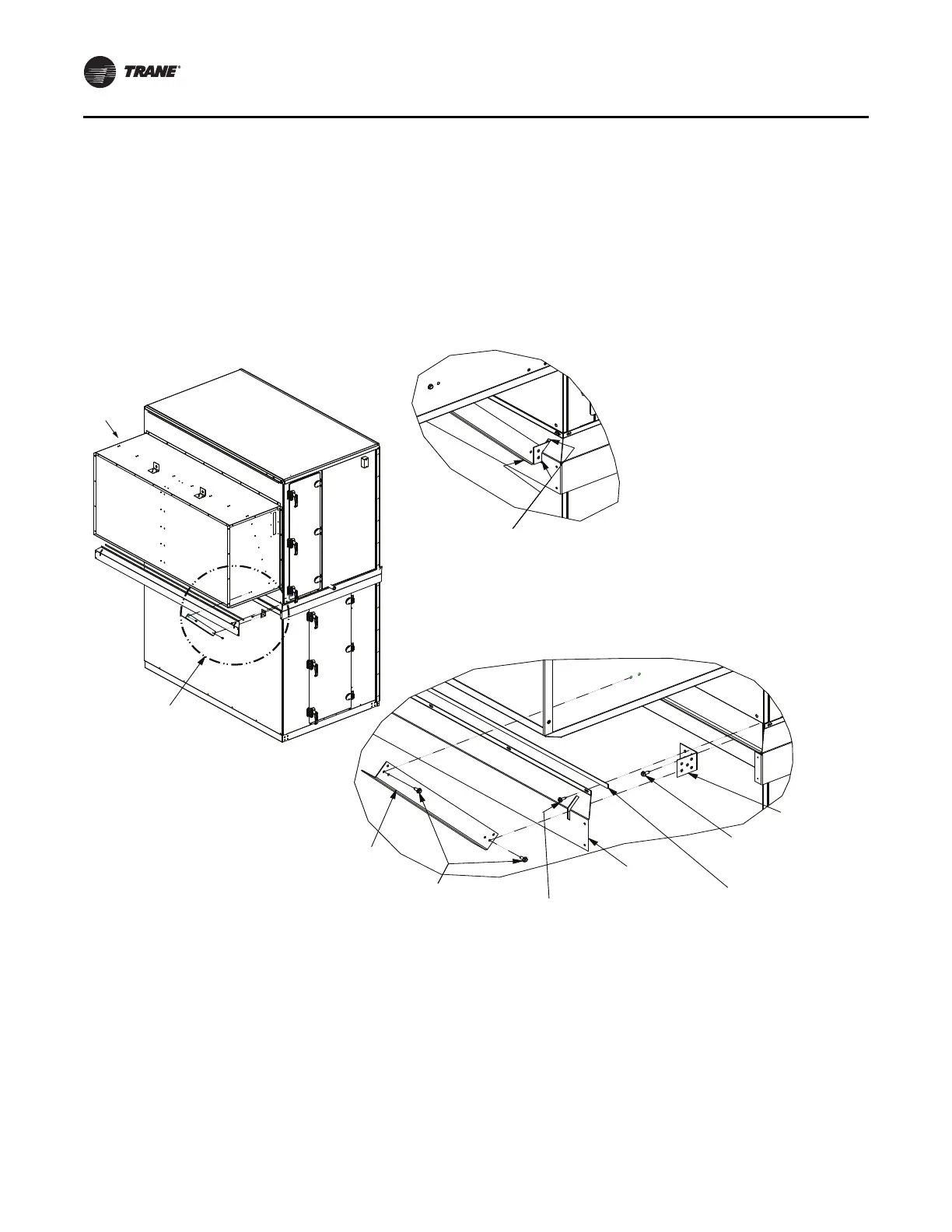
Install flashing and hood
1. See Figure 41. Secure two hood support brackets (Item
15) to base rail with screws (Item 17).
2. Apply Butyl tape (Item 8) to flashing (I
tem 9) and place
over hood support brackets (Item 15) using cut in
flashing and secure to base rails with screws (Item 4).
3. See “Hood Installation,” p. 24 for hood installation
instruc
tions.
4. Se
cure hood support angles (Item 16) to hood support
brackets (Item 15) and to the hood side p
anels with
screws (Item 17).
5. Apply caulk (Item 14) around hood support bracket
(Item
15), hood support angle (Item 16), and cutout in
perpendicular-
to-airflow flashing (Item 9) to ensure
water-tight seal.
Figure 41. Stacked unit assembly
(4) Screw:
10-16 x 0.750
self driller
(8) Tape:
0.12T x 1.00W
gray Butyl
(9) Guard:
perpendicular
to airflow flashing
Apply caulk
(14) Adhesive/sealant:
flex polyurethane
(15) Bracket:
hood support
(16) Angle:
hood support
(17) Screw:
0.250-14 x 0.750
self driller
Hood
See Detail A
Detail A
Assembled View
(17) Screw:
0.250-14 x 0.750
self driller
Detail A
External Raceway Assembly
For air handling units with factory-installed power wiring
extending from the first level to the second level, wiring
must be connected and assembled in a raceway. See
Figure 42.
1. Cut zip ties. Remove protectiv
e foam
cover from
connectors.
2. Attach stacked raceway harness connectors, mat
ching
connec
tor colors on the high voltage side and
connector numbers on the low voltage side.
3. Verify conduit size.
4. Attach covers.
5. Secure conduit. Space tie-downs no gr
eater than 10
inches. Locate cut-screw behind conduit.
Part numbers:
• Indoor
– External Raceway Kit: KIT09713
• Outdoor
– External Raceway Kit - Top: KIT16191