Figure 49. Filter block-off placement
Component Installation
38 CLCH-SVX013B-EN
Duct Connections
All duct connections to the air handlers should be installed
in accordance with the standards of the National Fire
Protection Association (NFPA):
• NFPA 90A for installing air conditioning and ventilating
systems other than res
idence type.
• NFPA 90B for residence-type warm air heating and air-
conditioning systems.
See unit submittal documentati
on for additional duct
mounting information.
Fan Discharge Connections
To ensure the highest fan efficiency, duct turns and
transitions must be made carefully, minimizing air friction
losses and turbulence. Proper ductwork installation, as
outlined by such organizations as Sheet Metal and Air
Conditioning Contractors National Association, Inc.
(SMACNA), should be followed closely.
Indoor unit fan sections with rectangular or round
op
enings should have flanged ductwork attached to
bottom panel opening. When using lined ducts, the
insulation should not obstruct the discharge opening. For
plenum fan sections with bell mouth fittings, see “Bell
Mouth Discharge Connections,” p. 40.
Damper Connections
Standard damper sections include mixing sections, filter
mixing sections, face dampers sections, and internal face-
and-bypass sections. There are two damper blade
configurations available - parallel-blade and opposed-
blade. Traq™ dampers are another type of damper
available in mixing box sections.
Ductwork attached to the standard damper sections
sh
ould be sized to fit the opening of the damper. Duct
opening dimensions are provided in the submittals. When
using lined duct, ensure that the insulation does not
obstruct the damper opening (see Figure 50 and
Figure 51).
Note: Da
mper blades should be checked for proper
operatio
n from full-open to full-closed position
before unit start up. Damper blade positioning may
have changed due to shipping and handling
vibrations.
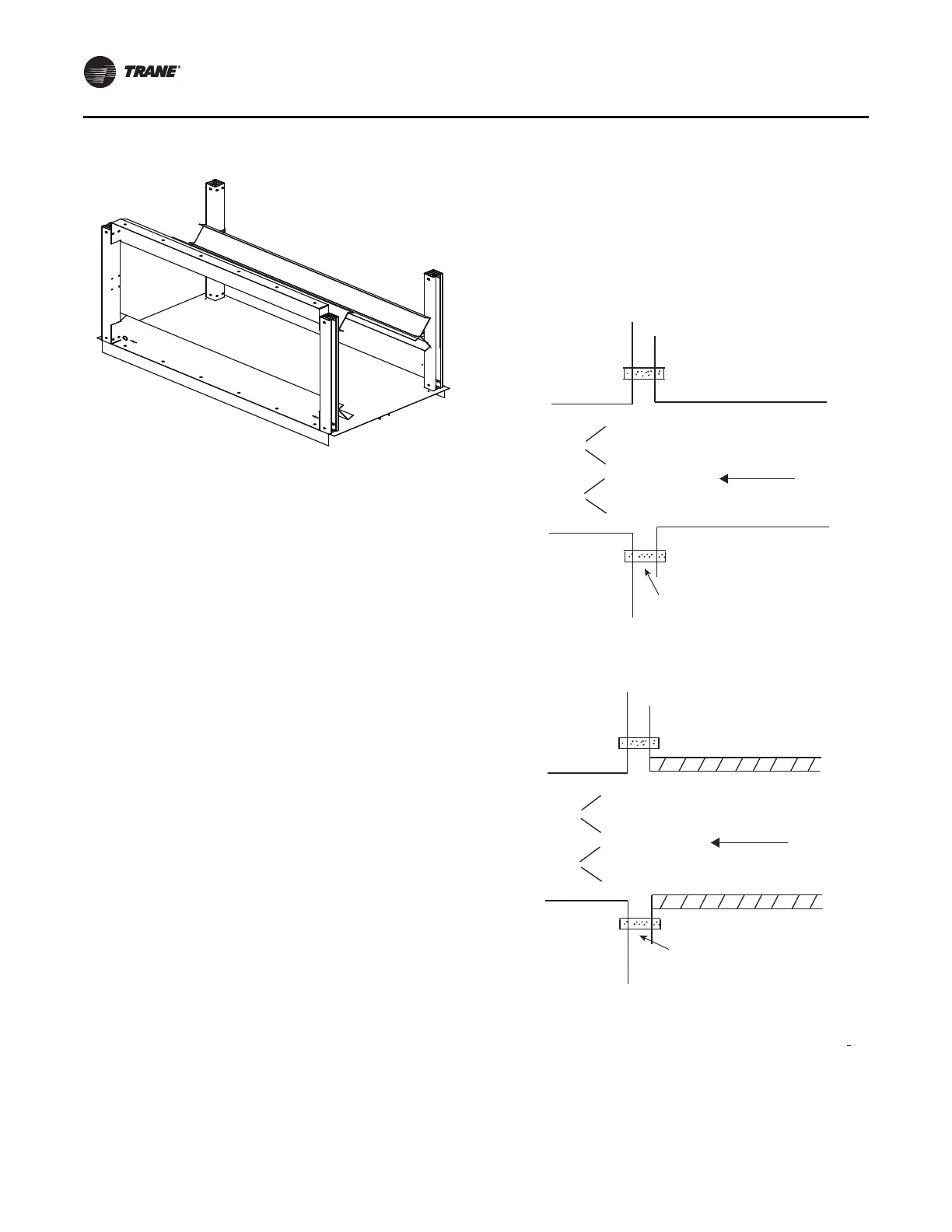
Figure 50. Typical duct flat/flange connection -
uninsulated or externally insulated
Unit
section
Flat connection
Uninsulated duct
Airflow
Figure 51. Typical section with duct flat/flange
connection- internally insulated
Unit
section
Flat connection
Insulated duct
Airflow
Bottom Opening Duct Installation
1. Install gasket to duct flange to ensure air tight seal.
2. Install duct into place underneath framed opening in
unit base per Figure 52. Refer to factory curb layout
provided wi
th unit submittals for duct size and
location.