Start-Up
70 CLCH-SVX013B-EN
Maintenance
For a typical HVAC environment - especially with upstream
filtration - there should be little to no required
maintenance. In extreme cases or for mishaps (bearing
grease in the taps for example), the flow meter is easily
cleanable. The fan inlet airflow measuring system is
extremely simple: a few pressure taps, a few fittings, and
some tubing. Although unlikely, if any tap were to get
clogged, simply disconnect each side of the transmitter
and blast air in a reverse direction through the system.
Constant K Factor
The constant K factor is unique for each fan and is
primarily a function of the area and other geometric
properties of the fan inlet. Pre-engineered factors are
available from the factory for fan types where the airflow
measurement system is available.
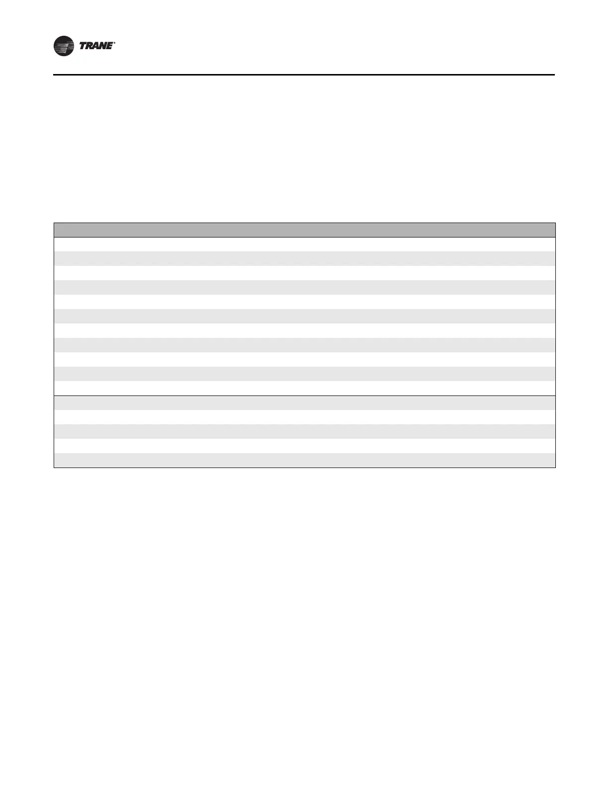
Table 15. Constant K Factors
Fan Size (inches)/Type Fan Class Fan Name K-Factor
10.50 AF direct-drive plenum Any 10 TF, 10 TR, 10 UF, 10 UR 576
12 AF direct-drive plenum Any 12 TF, 12 TR, 12 UF, 12 UR 945
13.50 AF direct-drive plenum Any 13 TF, 13 TR, 13 UF, 13 UR
965
15 AF direct-drive plenum Any 15 TF, 15 TR, 15 UF, 15 UR 1227
16 AF direct-drive plenum Any 16 TF, 16 TR, 16 UF, 16 UR
1519
18 AF direct-drive plenum Any 18 TF, 18 TR 1822
20 AF direct-drive plenum Any 20 TF, 20 TR
2186
22 AF direct-drive plenum Any 22 TF, 22 TR 2714
24 AF direct-drive plenum Any 24 TF, 24 TR
3285
27 AF direct-drive plenum Any 27 TF, 27 TR 3998
30 AF direct-drive plenum Any 30 TF, 30 TR
4945
15.70 motorized impeller Any 15VP 1747
17.70 motorized impeller Any 17VP
2231
19.70 motorized impeller Any 19VP 2612
22.00 motorized impeller Any 22VP
3233
24.80 motorized impeller Any 24VP 4071
Note: This table to be used for the updated tap design - mid-2014 and beyond. Refer to prior editions of this publication for the previous design.