S9V2-SVX001-1B-EN
41
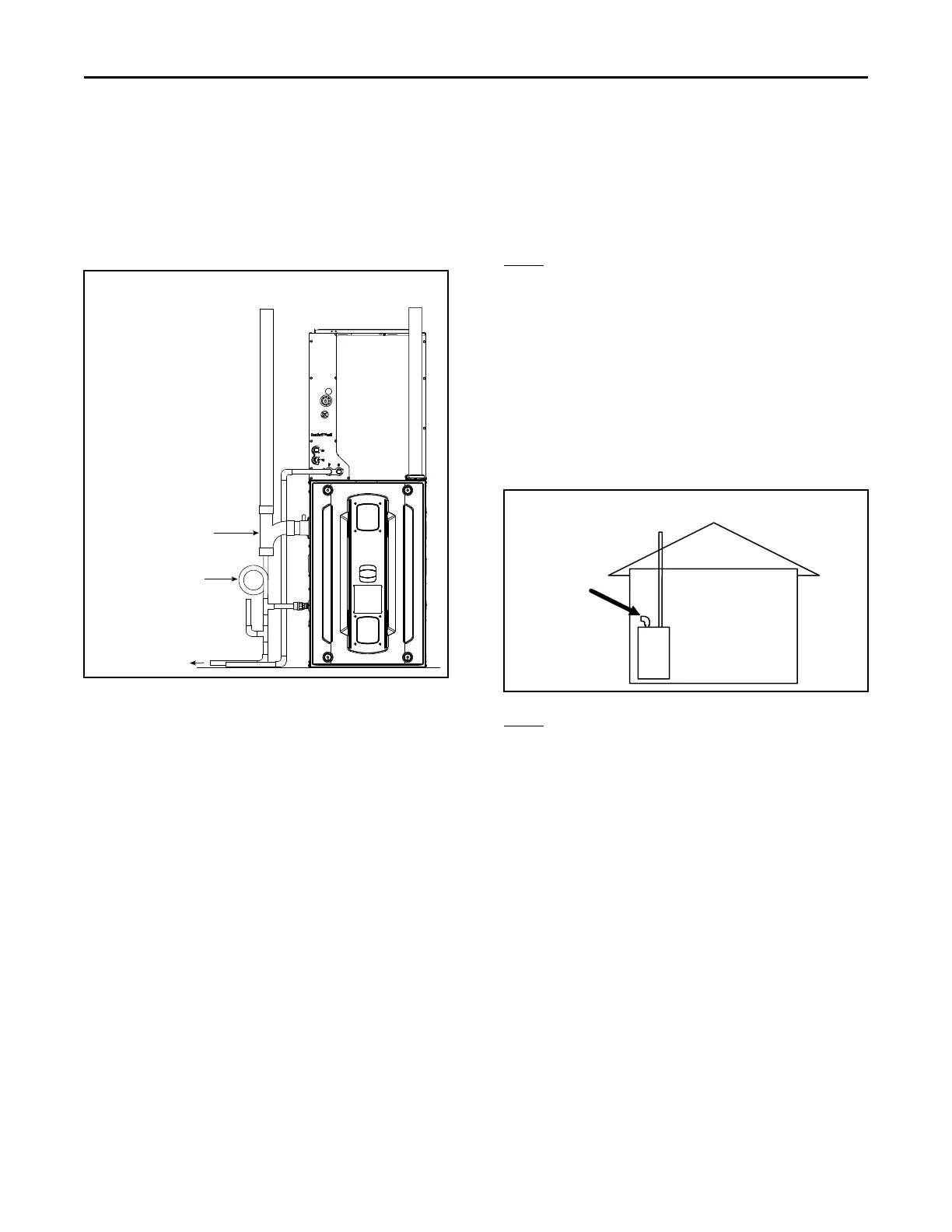
OOppttiioonn 33 —— SSiiddee ccoommbbuussttiioonn aaiirr iinnttaakkee
If sloping the combustion air intake pipe is not
possible, install an approved DWV Tee as close to the
furnace as possible with drain and trap.
NNoottee:: Combustion air drain fitting must remain capped
if not using the drain function. See “Condensate
Drain Instructions,” p. 66 section.
Combustion air
intake
Combustion air
exhaust
Option 3
To an approved
vented drain
Field fabricated trap
Approved DWV Tee
Primary drain vent stack must
terminate below the bottom of
the condensate trap
Vent Terminations
For DDIIRREECCTT VVEENNTT AAPPPPLLIICCAATTIIOONN:: The Furnaces must
be vented to the exterior of the house and combustion
air MUST come through the inlet air pipe from
OUTSIDE AIR.
NNoottee:: BAYVENT* accessories can be used for inlet and
outlet terminals when the pipes do not exit the
structure together. For Canadian applications,
venting systems must meet ULC-S636
requirements.
For NNOONNDDIIRREECCTT VVEENNTT AAPPPPLLIICCAATTIIOONN:: The Furnace
shall be vented to the exterior of the house, but
combustion air may enter from the surrounding area as
long as combustion air requirements are met. (See AIR
FOR COMBUSTION AND VENTILATION)
VVeenntt tteerrmmiinnaattiioonnss
• BAYVENT200B
• BAYAIR30AVENTA
Vent terminations — Canadian applications. Meets
ULC-S636 requirements.
• BAYVENTCN200B
• BAYAIR30CNVENT
FFUURRNNAACCEE VVEENNTT // IINNLLEETT PPIIPPEE IINNSSTTAALLLLAATTIIOONN IINN
TTWWOO PPRREESSSSUURREE ZZOONNEE CCOONNFFIIGGUURRAATTIIOONNSS AARREE
NNOOTT AALLLLOOWWEEDD
NNoottee:: For single pressure zone applications, see the
Horizontal Venting section.
The following are EEXXAAMMPPLLEESS OONNLLYY..
EEXX.. 11 --
Example 1 shows the vent pipe exhausting through the
roof and the inlet air coming from the interior of the
house. The inlet air coming from the interior of the
house must meet combustion requirements for area,
etc., as shown in the section AIR FOR COMBUSTION
AND VENTILATION in this document.
NNoottee:: If only the flue gas pipe is to the outside of the
structure, a straight section of pipe (long enough
to exit the Furnace cabinet) must be attached to
the inlet air side with an elbow (which is 5 to 10
equiv. ft.) installed on the end to prevent dust
and debris from falling directly into the Furnace.
EEXX.. 22 --
The inlet air does not have to come from outside the
structure. Example 2 shows the inlet air, may come
from the attic if the requirements for combustion air
are met as shown in the section AIR FOR
COMBUSTION AND VENTILATION.
NNoottee:: If only the flue gas pipe is to the outside of the
structure, a straight section of pipe (long enough
to exit the Furnace cabinet) must be attached to
the inlet air side with an elbow (which is 5 to 10
equiv. ft.) installed on the end to prevent dust
and debris from falling directly into the Furnace.
FFuurrnnaaccee GGeenneerraall IInnssttaallllaattiioonn

 Loading...


