40
S9V2-SVX001-1B-EN
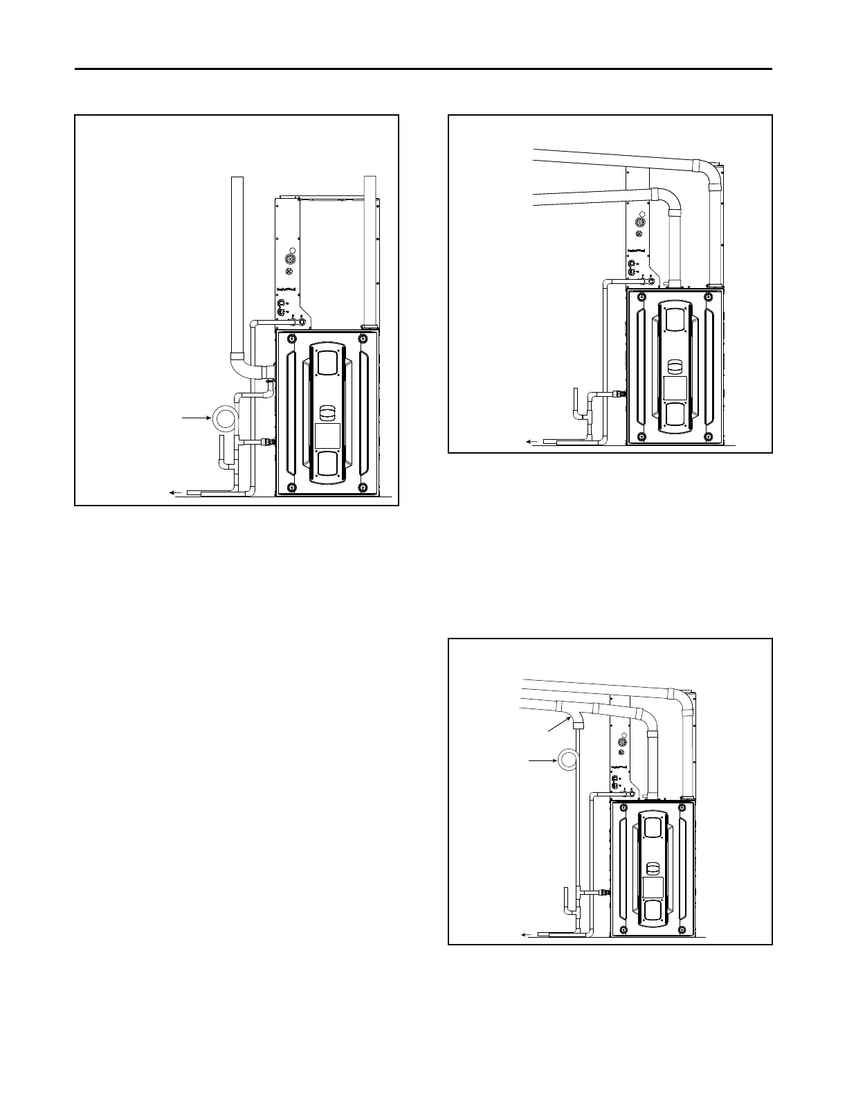
Figure 3. Upflow Side Entry
Combustion air
intake
Combustion air
exhaust
To an approved
vented drain
Field fabricated trap
Primary drain vent stack must
terminate below the bottom of
the condensate trap
Special Case Venting
SSppeecciiaall iinnssttrruuccttiioonnss ffoorr ddiirreecctt vveenntt ffuurrnnaaccee aaiirr
iinnttaakkee..
In certain applications, particularly when the furnace is
located in a basement, there are certain conditions that
can be met where warm humid air from the outside is
drawn into combustion air piping. If the area where the
piping is located is conditioned below 70° F,
condensation could occur inside the piping and
ultimately drain into the furnace compartment, which
could lead to premature component failure.
We recommend following one of the options to prevent
this condition from occurring and possibly damaging
components within the furnace:
NNoottee:: Inlet air piping is not considered to be part of the
venting system. The inlet air piping may be
made from PVC.
OOppttiioonn 11
If possible, slope the inlet combustion air piping away
from the furnace. Condensation that may occur will
now drain outside of the home. The combustion air
exhaust must be sloped back to the furnace.
NNoottee:: Combustion air drain fitting must remain capped
if not using the drain function. See “Condensate
Drain Instructions,” p. 66 section.
Option 1
Slope equals 1/4” per foot
To an approved
vented drain
Combustion air
intake
Combustion air
exhaust
Primary drain vent stack must
terminate below the bottom of
the condensate trap
OOppttiioonn 22 —— TToopp ccoommbbuussttiioonn aaiirr iinnttaakkee
If sloping the combustion air intake pipe is not
possible, install a DWV Tee as close to the furnace as
possible with drain and trap to prevent condensation
from occurring in the furnace cabinet. Do not tee AC
condensate and combustion air condensate trap
together.
NNoottee:: Combustion air drain fitting must remain capped
if not using the drain function. See “Condensate
Drain Instructions,” p. 66 section.
Option 2
To an approved
vented drain
Field fabricated trap
Combustion air
intake
Combustion air
exhaust
Primary drain vent stack must
terminate below the bottom of
the condensate trap
Approved DWV Tee
Slope equals 1/4” per foot
FFuurrnnaaccee GGeenneerraall IInnssttaallllaattiioonn

 Loading...


