S9V2-SVX001-1B-EN
39
33”” VVeennttiinngg rreeqquuiirreemmeennttss
IImmppoorrttaanntt:: To determine if your application requires 3”
venting, see the Maximum Vent Length
Table.
IImmppoorrttaanntt:: Horizontal venting application must use the
2” x 3” offset reducing coupling. Vertical
venting applications do not require the
reducing coupling to be offset.
NNoottee:: If your furnace comes with a factory supplied 2"
X 3" offset reducing coupling it is used for 3"
vent pipe installation. Make sure the marking
"TOP" is located on the top side of the pipe in
horizontal venting applications. The straight side
of the coupling must be on bottom for proper
drainage of condensate.
LABEL
SAYS
“TOP”
2" TO 3" COUPLING
CPL01544
BAYREDUCE may be
used in Canadian
applications to meet
ULC-S636
CPL01544 IS FACTORY
SUPPLIED ONLY WITH THE
120,000 BTUH FURNACE
MODELS
NNoottee:: For Canadian applications, BAYREDUCE 2” x 3”
offset reducing coupling meets ULC-S636
requirements. Make sure the marking "TOP" is
located on the top side of the pipe. The straight
side of the coupling must be on bottom for
proper drainage of condensate in horizontal
venting.
2" TO 3" COUPLING
CPL01544 IS FACTORY
SUPPLIED ONLY WITH THE
120,000 BTUH FURNACE
MODELS
CPL01544
BAYREDUCE may be
used in Canadian
applications to meet
ULC-S636
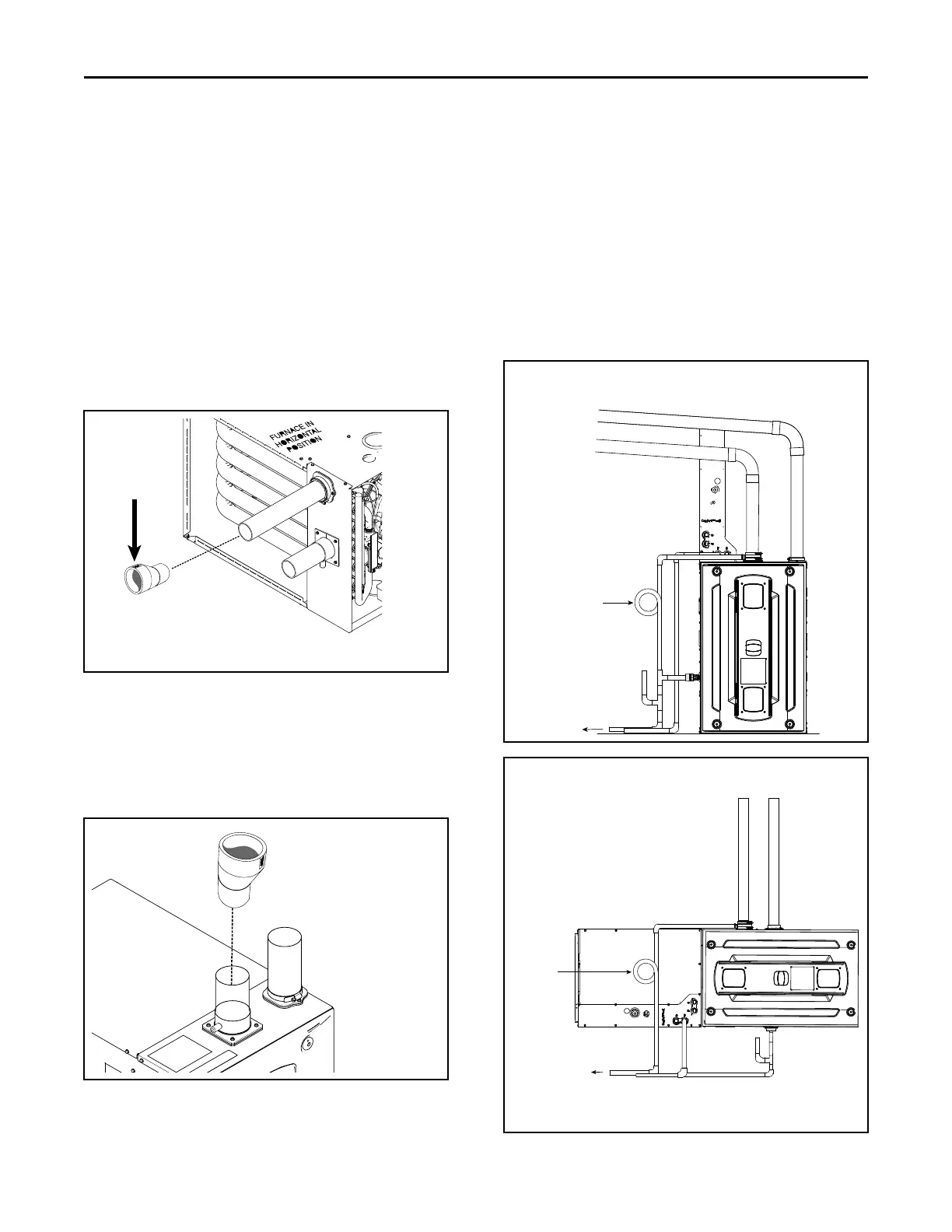
Typical Venting
This combustion air intake has a built-in condensate
collection system. Condensate that may collect is
drained by field supplied 1/2" ID tubing. The tubing
must be routed to form a trap and water seal ( see
Figure 1, p. 39, Figure 2, p. 39, and Figure 3, p. 40).
A field supplied hose clamp is recommended but not
be required. The tubing is not under pressure.
Combustion air piping must be square cut and de-
burred for proper drainage. For side entry combustion
inlet applications, ensure the drain is pointed
downwards.
Figure 1. Upflow Top Entry
To an approved
vented drain
Combustion air
intake
Combustion air
exhaust
Slope equals 1/4” per foot
Field fabricated trap
Primary drain vent stack must
terminate below the bottom of
the condensate trap
Figure 2. Horizontal Top Entry
Combustion air
intake
Combustion air
exhaust
Field
fabricated
trap
To an approved
vented drain
Note: Primary drain vent stack must terminate below the
bottom of the condensate trap.
FFuurrnnaaccee GGeenneerraall IInnssttaallllaattiioonn

 Loading...


