10
S9V2-SVX001-1B-EN
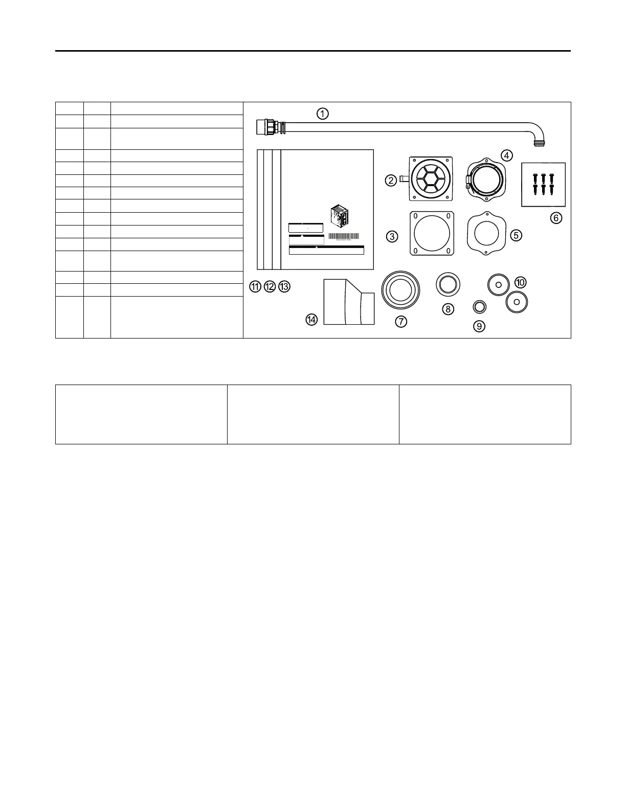
Document Pack Contents
Item Qty. Description
SSAAFFEETTYY WWAARRNNIINNGG
Only qualified personnel should install and service the equipment. The installation, starting up, and servicing of heating, ventilating, and air-conditioning
equipment can be hazardous and requires specific knowledge and training. Improperly installed, adjusted or altered equipment by an unqualified person
could result in death or serious injury. When working on the equipment, observe all precautions in the literature and on the tags, stickers, and labels th at
are attached to the equipment.
September 2023
SS99VV22--SSVVXX000011--11B --EENN
Upow/Horizontal and Dedicated Downow
Gas-Fired, Direct/Non-Direct Vent, 2–Stage
Condensing Variable Speed Furnaces
UUpp fflloo ww ,, CCoo nnvveerr ttiibb ll ee ttoo
HHoorrii zzoo nnttaallRRiigghhttoorr
HHoorrii zzoo nnttaallLLeefftt
S
9V2B040U3PSC
S9V2B060U4PSC
S9V2B080U4PSC
S9V2C080U5PSC
S9V2C100U5PSC
S9V2D120U5PSC
DDooww nnffll ooww OOnn llyy
S9V2B040D3PSC
S9V2B060D3PSC
S9V2B080D4PSC
S9V2C100D5PSC
S9V2D120D5PSC
NNoo ttee::Graphics in this document are for
representation only. Actual
model may differ in appearance.
Installation, Operation, and Maintenance
CAUTION
!
Failureto follow this Cautioncould result in propertydamage or personal injury.4GXC* and
4MXC*coils installed onupflow furnaces in vertical,horizontal left, or horizontalright
orientationswithout a factoryinstalled metal drainpan shield must use a MAY*FERCOLKITAA
kit.Coils installed on upflowfurnaces must have drainpans that are suitable for400° F
(205°C)or have a metal drainpan shield. Downflow furnacesdo not require a metaldrain pan
shieldor the use of theMAY*FERCOLKITAAkit.
COILREQUIREMENT!
WARNING
FIRE HAZARD!
Failureto follow thisWarning could result in property damage, severepersonal
injury,or death.
This Warningapplies toinstallations with a
ammablerefrigeration system.
The furnacemust be powered except for service.The furnace shall be installed
and connectedaccording to installation instructions and wiring diagrams that
areprovided with the evaporator coil.
1 1 Condensate Drain Tube Assembly
2 1 Inlet Vent (2”- ADP01586 and 3” -
ADP01587)
(a)
3 1 Inlet Vent Gasket
4 1 Outlet Vent Assembly
5 1 Outlet Vent Gasket
6 6 Screws
7 1 Condensate Trap Grommet
8 1 Plug — Condensate/Gas
9 1 Plug — Electrical
10 2 Grommet — Condensate/Gas
11 1 Installation, Operation, and
Maintenance
12 1 Owner Guide
13 1 Limited Warranty
14 1 2” to 3” Coupling — CPL01544
(b)
(a)
3” inlet vent supplied with S9V2D120U5PS and S9V2D120D5PS only. 2” inlet vent supplied with all other models.
(b)
Supplied with S9V2D120U5PS and S9V2D120D5PS only.
Part List
• Igniter
• Flame Sensor
• In-shot Burner(s)
• Gas Valve
• Inducer Assembly
• Blower Motor
• Blower Wheel
• IFC (Integrated Furnace Control)
• Pressure Switch(es)
• Main Thermal Limit
• Roll-Out Switch(es)
• Reverse Air Switch(es)
AAcccceessssoorriieess

 Loading...


