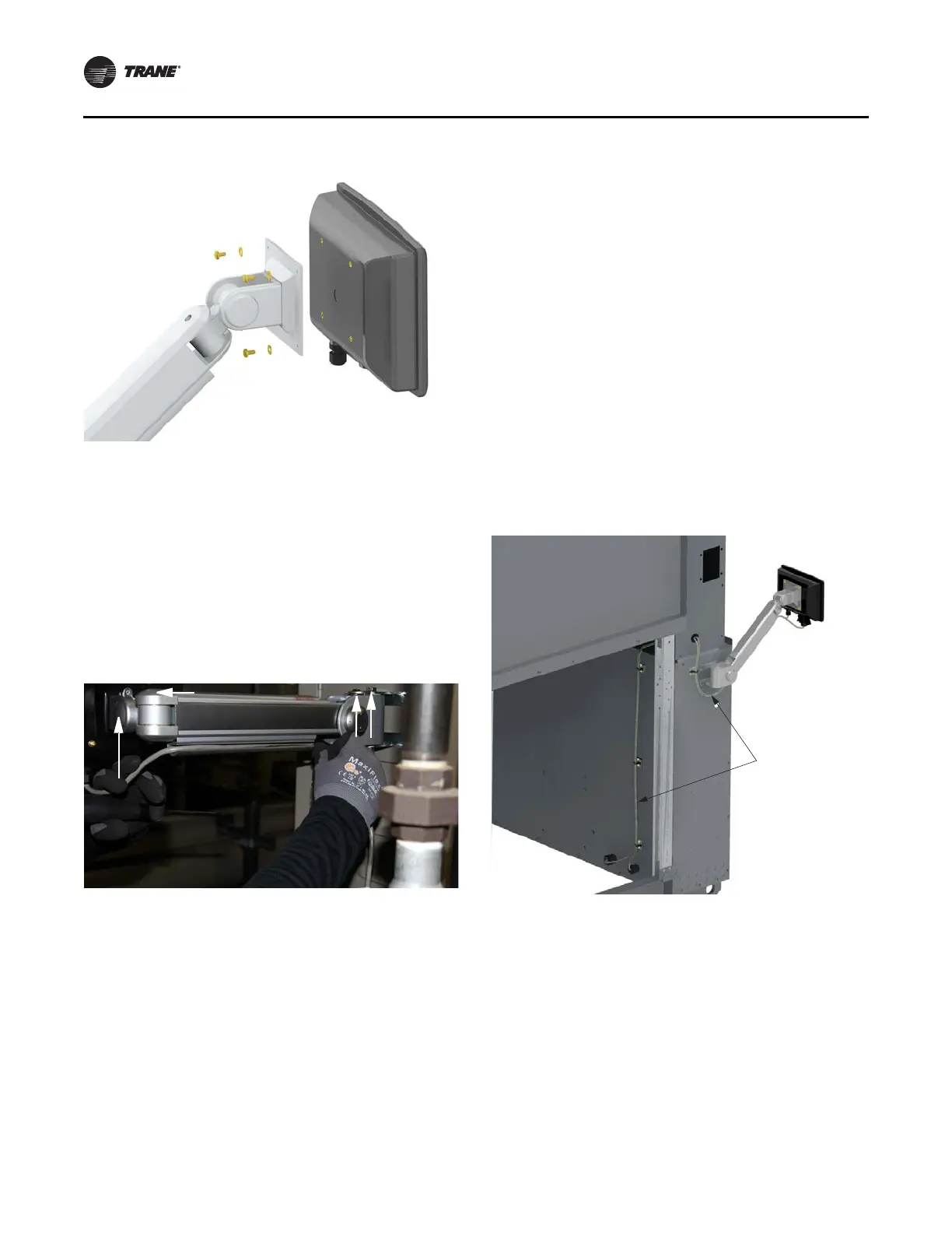
Figure 17. TD7 installation
Installation
16 RCDA-SVN002C-EN
6. Set the arm tension so the display does not spring up
or sag.
Adjusting the Tracer
®
AdaptiView™ Display Arm
There are three joints on the display arm that allow the
Tracer
®
AdaptiView™ display to be positioned at a variety
of heights and angles (see Figure 18, p. 16, items labeled
1, 2, and 3).
Figure 18. Joint locations on the display arm
1. At each joint in the display arm there is either a hex bolt
(1 and 2) or hex screw (3). Turn the hex bolt or screw
in the proper direction to increase or decrease tension.
Note: Ea
ch hex bolt or screw is labeled with “loosen”,
“tighten” or ‘”
+/-” indicators.
2. Joint 3 has a 6 mm hex screw controlling the tension
on a gas
spring, which allows the Tracer AdaptiView
display to tilt up and down.
3. Joints 1 and 2 are covered by a plastic cap. Remove the
plastic
cap to access
the hex bolt. Adjust using a
13 mm wrench as necessary.
4. To adjust the swivel of the Tracer
AdaptiView display
(the spin right and left similar to the steering wheel on
a car), adjust the hex bolt located inside the display
arm back plate. This adjustment needs to be done
BEFORE attaching the display. Use a 9/16 in. or 14 mm
wrench.
5. Use a 13 mm wrench to adjust the
bolt (item l
abeled 4
in Figure 18) that allows the entire displ
ay arm to
swivel to the left and right.
Routing Cables
1. Install the side panel.
2. Route the TD7 cables through the hole in the side panel
and insta
ll the split grommet. Run the cables along the
back side of the panel, and through the 1/2” and 3/4”
cord grips.
3. Install the cord grip split grommets and tighten nuts to
seal the
cords.
4. Secu
re cable with the adh
esive moun
ted zip ties
provided in the kit. See Figure 19, p. 16.
Figure 19. TD7 cable routing
 Loading...


