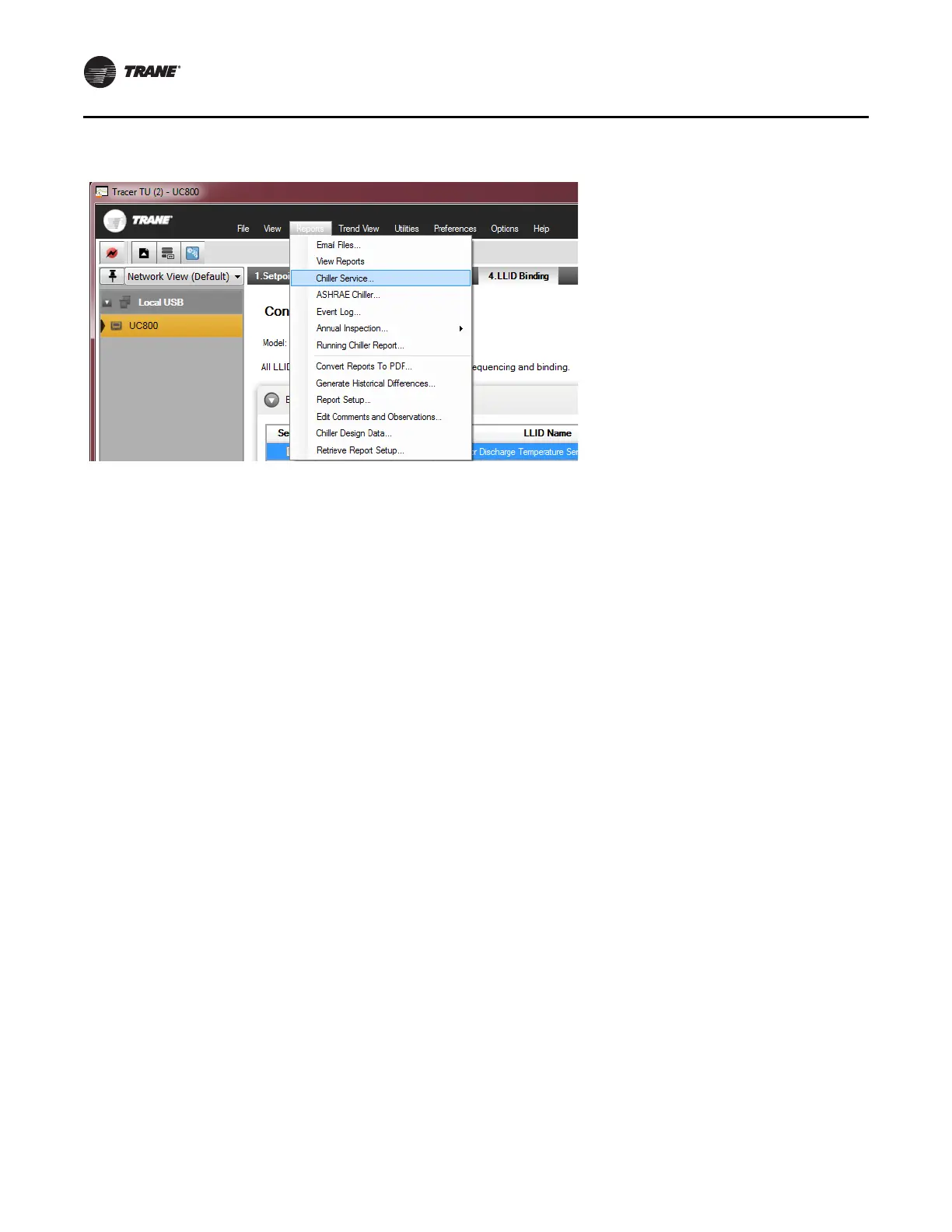
Figure 33. Chiller service report (Tracer TU)
Installation
24 RCDA-SVN002C-EN
11. Save a copy of the Chiller Service Report. This report
can be compared to the report that was saved from
KestrelView to ensure that all settings are correct.
Note: T
his step produces backup configuration data
in th
e case the UC800 configuration becomes
corrupt.
a. Access the Equipment Utilities section of Tracer TU
b
y clicki
ng the wrench symbol on the right hand
side of the screen.
b. Click the Configuration tab.
c. At the bottom of the screen, click the Save File
but
ton.
d.
In the Browse for Folder window, click Make New
Fo
lder.
e.
A folder will be created with the name New Folder;
this ca
n be renamed later. The path to the folder will
be:
C:\Programs\Trane\TracerTU\Program\Plugins\UC
DataBaseDAL\New Folder
f. Select the New Fo
lder file.
g. Click the OK button.
h. The chiller configuration file will now be saved in
th
e New Folder
.
i. Compare the KestrelView report with the Tracer TU
rep
ort to validate configuration settings and
setpoints.
Options
Generic BAS Interface
For the following option installations, see Figure 39, p. 32,
unit schematic and upgrade schematic.
When ordered, controls are provided for hard-wired chiller
control.
Functions included are as follows:
• External Baseload Command
• Ice Building Control
• External Baseload Set-point
•RLA OUT
• Chilled Water Set-point IN
• Customer Current Limit IN
• Ice Making Status
• Customer Programmable Relays
Tracer
®
Interface Control
The Tracer
®
AdaptiView™ controls can interface with
several BAS protocols. The UC800 control is able to
directly communicate with Modbus
®
and BACnet
®
systems. Additional control boards are available to
communicate with LonTalk
®
(COMM5) systems.
 Loading...


