Installation
RCDA-SVN002C-EN 17
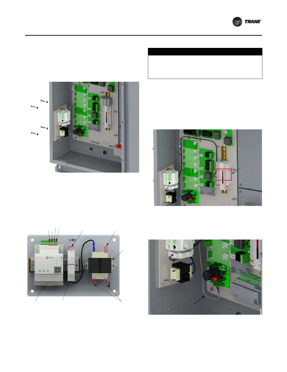
Back Plate Assembly
1. Using the 1/4-20 bolts, nuts and sealing washers
secure the back plate assembly to the side panel. See
Figure 20, p. 17.
Figure 20. Back plate installation
Note: See schematic 50711
917, shown in Figure 40, p. 34,
for the following steps.
2. Ensure one terminal on the line side of the transformer
is connected t
o the fuse on the backplate assembly by
a 14 AWG wire.
See Figure 21.
Figure 21. Back plate connections
For the following steps, see Figure 21 and Figure 40, p. 34.
NOTICE:
Transformer Damage!
Failure to follow instructions below could result in
transformer damage. Be sure to connect fuse on back
plate to correct terminal on the unit.
3. Using the 14 gauge wire provided in the kit connect the
fuse on the backplate assemb
ly to one of the terminals
(1-8) on TB5.
4. Using the 14 gauge wire and terminal provided in the
kit connect
the “Line” side of the 24volt transformer on
the backplate to one of the terminals (9-16) on TB5.
Figure 22. Back plate wire routing
5. Cut the connector off of cable X19051625020 and use
cable to conn
ect the UC800 to the power supply. See
schematic 50711917 (Figure 40, p. 34), Figure 21, p. 17,
and Figure 23
, p. 17.
Figure 23. Back plate UC800 to power supply
Notes:
• R — Red wire for 24VDC
• BK— Black wire fo
r grou
nd
• BL — Blue wire for MBUS+ connection
• GR — Gray wire for MBUS- connection
MBus-
MBus+
GND
+24V
Connect to
TB5 1-8
(120 VAC)
Connect to
TB5 9-16
(120 VAC)
120 VAC to
24 VAC
Transformer
Connect to
TD7 Power
(24 VAC)
Back Plate
Fuse
UC800
Connect Wire to
One of Terminals
on TB5 1-8
and 9-16
Route wires
from back plate
fuse and
transformer
to terminals
on TB5.
Connect PWR and COM
Wires from UC800 to
Power supply 1U2
 Loading...


