Installation
18 RCDA-SVN002C-EN
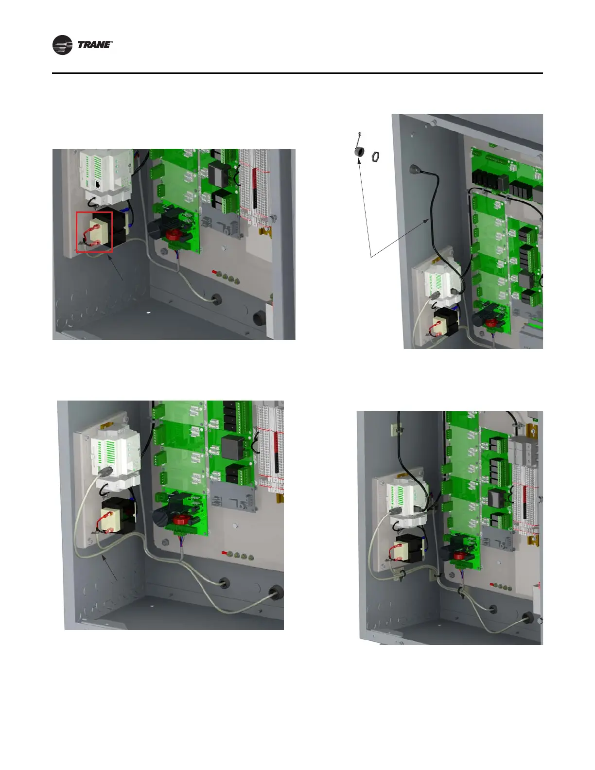
6. Crimp two terminals (X19180041070) to extension
X19051625030 from the TD7 and connect to the “Load”
Side of the transformer. See Figure 24, p. 18.
Figure 24. TD7 power connection
7. Connect the Ethernet cable from the TD7 to the UC800.
See Figure 25, p. 18.
Figure 25. TD7 communication connection
8. Install the USB Service port in the panel and connect to
the UC800. Install the USB
weatherproof cap. See
Figure 26, p. 18.
Figure 26. USB port installation
9. Secure all cables with the adhesive backed zip ties
provided in the kit. See Figure 27, p. 18.
Figure 27. Secure all cables
Connect TD7 Power
to Load Side
of Transformer
Connect Ethernet Cable
from TD7 to UC800
Install USB Port
Into Panel with
Weatherproof Cap
and Connect
to UC800
Secure ALL
Cables with
Adhesive
Backed
Zip Ties
 Loading...


