Installation
20 RCDA-SVN002C-EN
Programming the Tracer
®
AdaptiView™
1. Configure the UC800 using Tracer
®
TU. Refer to the
KestrelView report and write all the programming
entries in the order listed.
Note: For m
ore infor
mation regarding the use of the
Tracer TU service tool, installation, operation
and programming of the Tracer UC800
controller, operation of the control system, and
a guide to the diagnostics and troubleshooting
of the control system, please refer to the
following manuals:
• TT
U-SVN01*-EN (Getting Started Guide: Tracer
TU Service Tool)
• RTAC-SVX
01*-EN (Installation, Operation, a
nd
Maintenance, Series R Air-Cooled Helical Rotary
Liquid Chillers)
NOTICE:
Separate AC Power Required for
Computers when Working on Tracer
AdaptiView!
Failure to follow instructions below could result in
damage to the controller. When doing any service work
on a Tracer AdaptiView control system that requires
connecting a laptop computer running Tracer TU
service tool software to the UC800 controller, the
laptop must be operated from a SEPARATE AC power
source AT ALL TIMES. NEVER run the laptop on internal
battery power alone while connected to a UC800
controller! Should the computer’s internal battery die
or malfunction while connected to a UC800, fatal
corruptions could occur to the electronic files within
the controller that will render it completely inoperable
and unable to accept new programming, requiring it to
be replaced with new UC800. Damaging a UC800
controller in this manner is not covered under any
warranty!
2. Obtain a working AC power
adapter with which t
o
power the technician’s laptop.
3. Connect the computer with th
e Trac
er TU service tool
software to the service port of the Tracer UC800
controller with a USB type A/B cable.
4. Open Tracer TU.
Note: The UC800 ships with no s
oftware loaded.
When first connecting to Tracer TU, a pop-up
will direct you toward the software download
page.
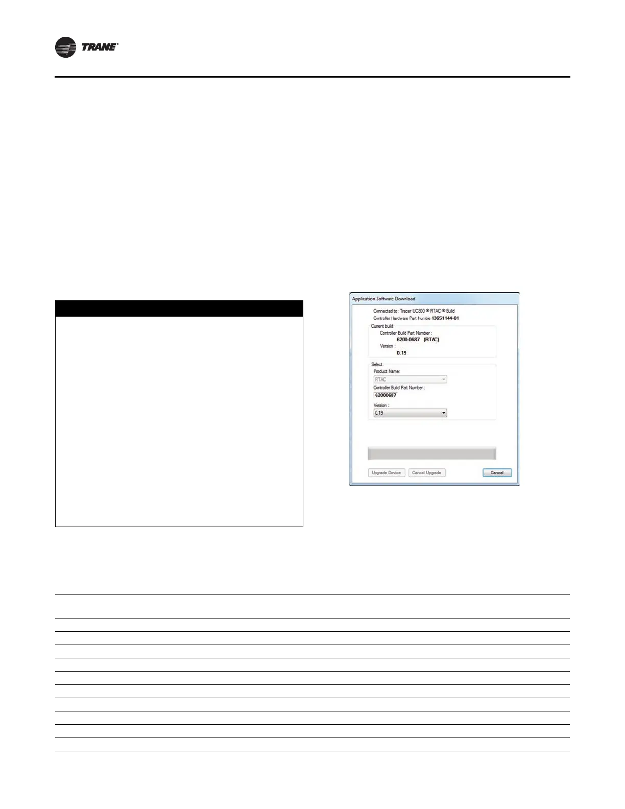
5. Select the appropriate product type (RTAC), and select
the la
test version listed.
6. Click the Upgr
ade Devic
e button when complete. See
Figure 29.
Figure 29. Application software download
7. Use the Chiller Report PDF to manually
copy the
configuration parameters in Tracer
®
TU. See Table 15
for correct mappings. After the configuration is saved,
Tracer TU will automatically proceed to LLID Binding
view. Check to see if any of the listed devices need to
be bound, indicated by a red box. See Figure 30, p. 23.
Table 15. Mapping table
Compressor
Frame Size
(a)
Manufacturing
Location
(b)
Unit Type
(Model Number Digit 12)
(c)
Unit
Voltage
(d)
Compressor
RLA
(e)
CT Meter
Scale
(f)
K1 Charmes N = Standard, A = Extra Efficiency 400 51 75
K1 Charmes H = High Efficiency 400 51 75
K2 Charmes N = Standard, A = Extra Efficiency 400 61 75
K2 Charmes H = High Efficiency 400 61 75
L1 Charmes N = Standard, A = Extra Efficiency 400 75 100
L1 Charmes H = High Efficiency 400 75 100
L2 Charmes N = Standard, A = Extra Efficiency 400 92 100
L2 Charmes H = High Efficiency 400 92 100
M1,M3 Curitiba, Pueblo, Taicang H = High Efficiency 575 90 100
M1,M3 Curitiba, Pueblo, Taicang N = Standard, A = Extra Efficiency 575 94 100
 Loading...


