Installation
RCDA-SVN002C-EN 13
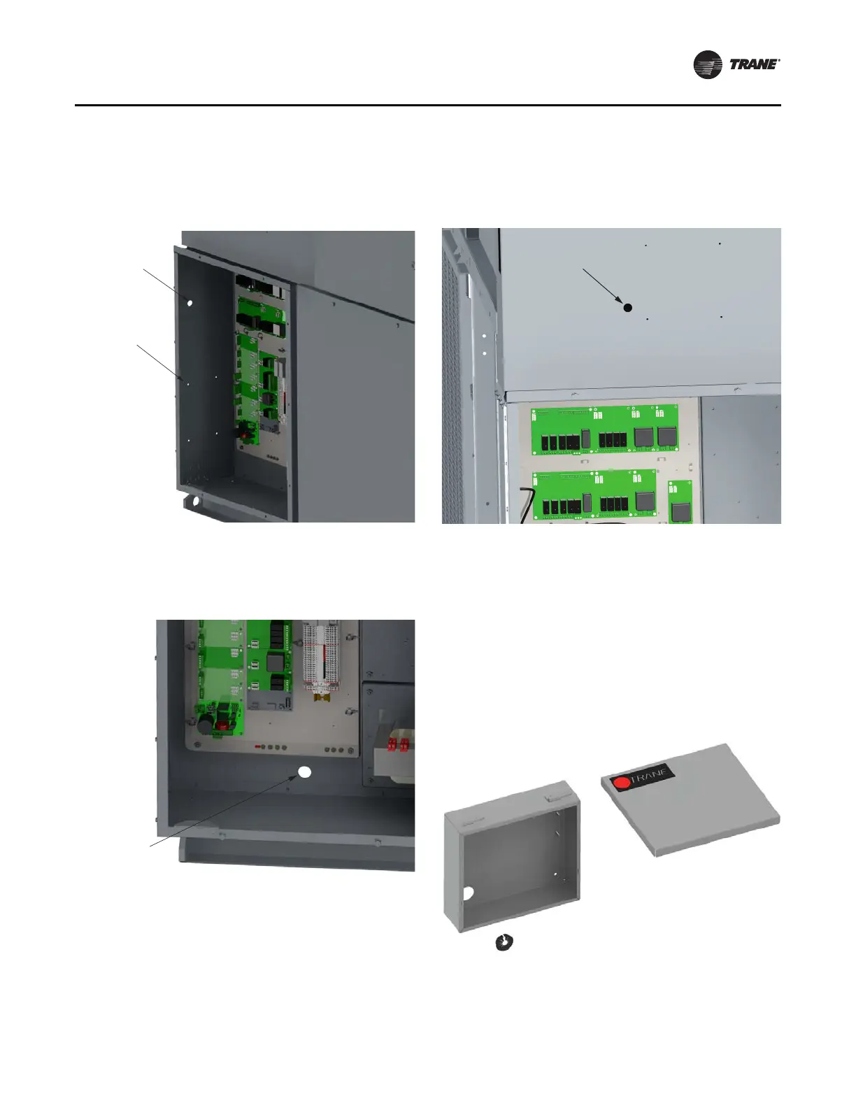
4. On either the side or front control panel, drill one 7/8”
hole for the USB Service Port.
Note: Length
from the USB port location to the back
plate should
be 18 inches or less.
Figure 5. Back plate assembly moun
t hole locations
5. Drill a 1-1/8” hole in the back of the control panel, just
below the control back plate. The ¾” cord grip will be
installed at this location. See Figure 6, p. 13.
Figure 6. Hole for 3/4” cord grip
6. After all holes are drilled, use a vacuum to remove any
dirt, debris, or metal filings that may have accumulated
inside of the control enclosure.
TD7 Enclosure Option
1. Use a 1-3/8” knockout punch to enlarge the 11/16”
diameter hole used to route the Dynaview™ cable.
Figure 7. Panel hole enlargement
2. Remove the lid from the TD7 enclosure, and
temporarily install the 1-1/4” split grommet. Aligning
the split grommet with the 1-3/8” hole created in the
previous step, place the enclosure on the panel. Level
and mark the 4 holes used to mount the enclosure.
Note: If the TD7 enclosur
e will not be mo
unted in the
same location as the DynaView, it must be
within 1 foot of the DynaView’s original
location. Plugs are provided in the kit to cover
the original DynaView mounting holes.
Figure 8. Enclosure
USB Port
Back Plate
Mounting
Holes
1-1/8” Hole
for 3/4” Cord Grip
Enlarge 11/16” Hole
to 1-3/8”
 Loading...


