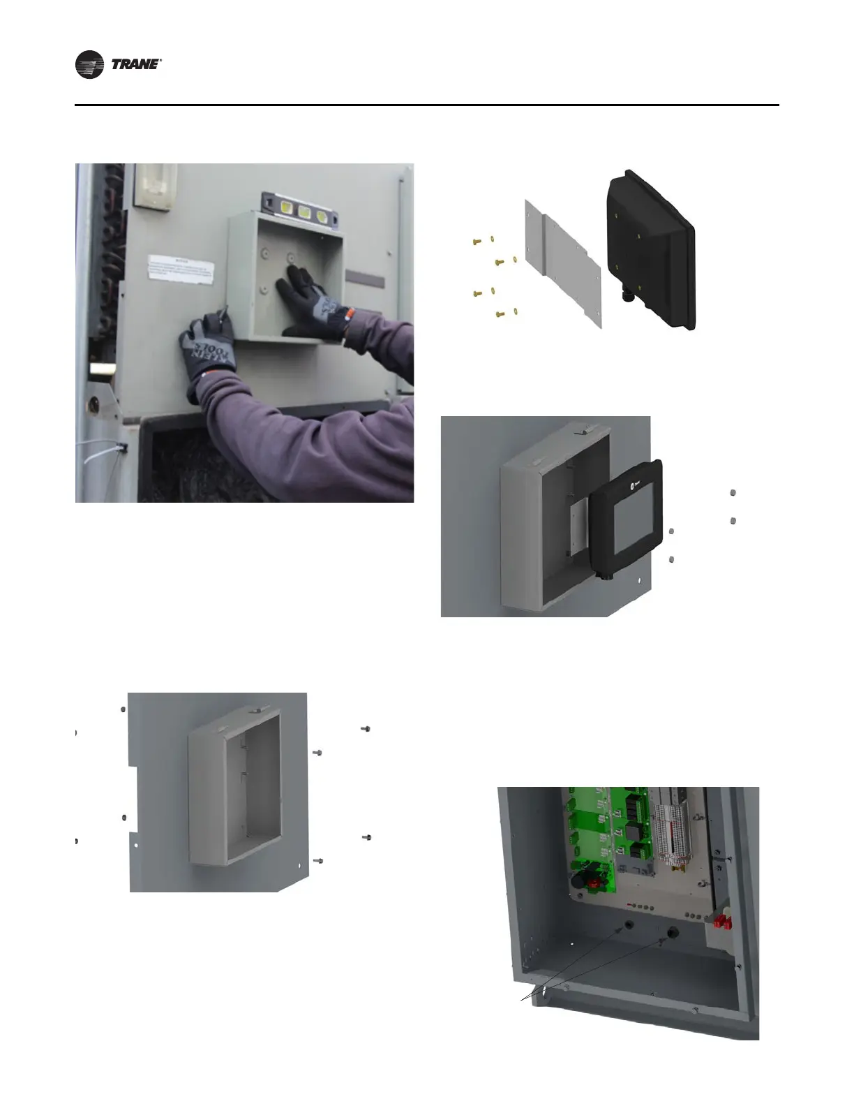
Figure 9. Leveling enclosure and hole marking
Installation
14 RCDA-SVN002C-EN
3. Remove the front panel or place a piece of wood in
between the panel and condenser tubes before drilling
any holes.
4. With a #2 (.221”) drill bit, drill the 4 holes marked in the
pr
evious step.
5.
Install the TD7 Panel to the unit with the 10-32 screws
and lock nuts.
Fig
ure 10. Enclosure to unit
6. Assemble the TD7 to the enclosure backplate using the
four brass M4 screws and washer provided in the kit.
Figure 11. TD7 to enclosure backplate
7. Assemble the TD7 to the enclosure with #10-32 lock
nuts. See Figure 12.
Figure 12. Assemble the TD7 to the enclosure
8. Connect wire extension X19051625030 and Ethernet
ca
ble X1907063202
0; route cables through the large
hole and install the provided grommet.
9. Route TD7 cables along the back side of the panel,
th
rough the ½” an
d ¾” cord grips.
10. Install the cord grip split grommets and tighten nuts to
seal the cords. See Figure 13, p
. 14.
Figure 13. Cord grip
Install
1/2” and 3/4”
Cord Grips
 Loading...


