Installation
RCDA-SVN002C-EN 27
LonTalk Integration
Reference manual ACC-SVN100*-EN, Table 18, Figure 39,
p. 32 and appropriate unit schematic for LonTalk
®
integration.
Table 18. LonTalk LLID description
and connections
Designation Mnemonic Part number Description
LLID
Connector Terminal(s)
Description/
Function Mating Connection
1U8 MOD02418 X13650845040
Comm 5
Interface
(LonT
alk
®
)
J11 1-4
Communication
(UC800)
IPC BUS (WB..)
J2
1-2 In
terface Port A and B
To Tracer or other Trane
Devic
e (Shie
lded,
Twisted Pair)
3-4 Interface Port A and B
To Next Unit ( Shie lded ,
Twiste
d Pair)
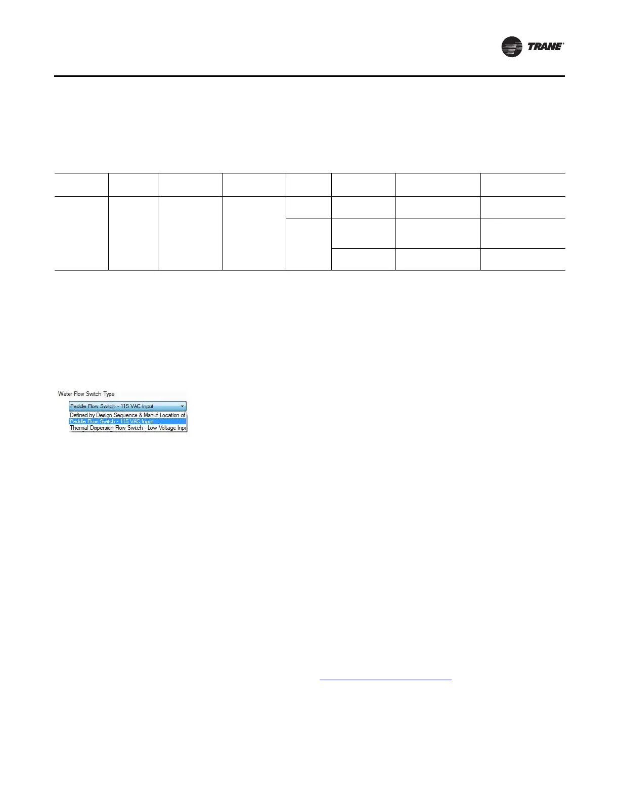
ifm efector Flow Switch
Note: This kit is designed to replace "paddle" style flow
switch utilizing a dual high voltage input LLID. This
kit is not a drop-in replacement for the current
production, low voltage input, thermal dispersion
flow switch. The Water Flow Switch Type must be
configured for "Paddle Flow Switch - 115VAC
Input".
Figure 35.
Flow switch configuration
The ifm efector flow switch kit includes:
• flow monitoring module (mounted inside control
panel)
•fl
ow sensor
• 10 meter sensor cable
• ½" NPT sensor adapter
• din rail and mounting screws.
Note: To
connect the flow monitoring module to the Dual
High Volta
ge Input LLID (1U11), field supplied 16
AWG wire meeting UL 1230 is required.
Using the provided din rail and 6mm screws, find a
su
itable lo
cation in the control panel to mount the flow
module. Complete the installation in accordance with the
instructions provided in the efector flow kit and schematic
shown in Figure 40, p. 34 and Figure 41, p. 35.
Thermal Dispersion Flow Switch Upgrade
The thermal dispersion flow switch upgrade is a set of
solid-state components with no moving parts or paddles
to stick or break. The kit includes an extended-length flow
probe, cabinet mounted control monitor, 1/2-inch NPT
adapter and 30-foot cable. The probe cable operates on
low voltage and is not required to be installed in conduit.
The probe system is designed for pipe diameters 4-inch
and larger. See wiring diagram 50711917(Figure 40, p. 34)
a
nd
the installation manual included in the upgrade kit for
specific instructions for mounting, wiring, and adjusting
the switch settings.
Global Connector Kit
The global connector kits allow a unit that has flat ribbon
cabling to be modified to the global connection cabling.
See “Global Harness Routing,” p. 36 for wiring diagrams
.
See Table 12, p. 9 through Table 14, p. 10 for the parts in
each kit.
Transducers and Sensors
The existing transducers and sensors are required to be
replaced. For the EXV and liquid level sensors install the
wire harness adapter male global connector to four-wire
ribbon cable (KIT13723). Refer to RTAC-SVX01*-EN
(Installation Operation and Maintenance: Series R Air-
Cooled Helical Rotary Liquid Chillers), PART-SVB16*-EN
(General Service Bulletin: Tracer
®
CH530/CH531
Pluggable Connector System) as well as the diagrams
provided in the kit.
Start-up
1. When the programming is completed and saved, shut
down power to the control panel and disconnect the
USB cable from the door of the control panel.
2. Restore power to the control panel. The chiller is now
ready
for normal startup and checkout procedures.
See to RTAC-SVX01*-EN for proper startup and
checkout procedures.
If you have further questions, contact Trane Global Parts
Technical Services. To contact them,
send a message to
ATechnicalService@trane.com.
 Loading...


