Installation
12 RCDA-SVN002C-EN
Shut Down Power
WARNING
Hazardous Voltage w/Capacitors!
Failure to disconnect power and discharge capacitors
before servicing could result in death or serious injury.
Disconnect all electric power, including remote
disconnects and discharge all motor start/run
capacitors before servicing. Follow proper lockout/
tagout procedures to ensure the power cannot be
inadvertently energized. For variable frequency drives or
other energy storing components provided by Trane or
others, refer to the appropriate manufacturer’s literature
for allowable waiting periods for discharge of
capacitors. Verify with an appropriate voltmeter that all
capacitors have discharged.
For additional information regarding
the safe discharge
of capacitors, see PROD-SVB06*-EN
1. Usi
ng lockout/tagout safety procedures, shut down the
chiller’s main power.
2. Open all starter and control panel disconnect switches
and
secure them in the open position.
3. Confirm that the power is off to the control panel of the
ch
iller.
Remove the DynaView™ Display
1. Remove the louver, side, and control enclosure panels.
See Figure 3.
2. Remove the 4 fasteners holding the DynaView display
to the Un
it.
3. Unplug the 4-wire Phoenix connector from the
Dyn
aView d
isplay and remove the DynaView display
from the unit.
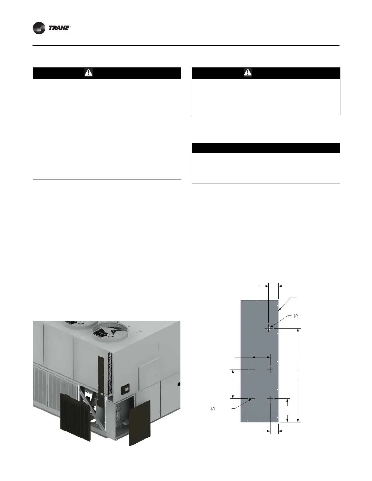
Figure 3. Louver panel removal
Prepare Unit for Installation
WARNING
Risk of Electrocution!
Failure to follow instructions could result in death or
serious injury. Before and during drilling operations
ensure that all electrical cables and wires are not in the
path of the drill bit.
1. Cover unit control cover back plate with plastic to
prevent
me
tal chips intrusion.
NOTICE:
Equipment Damage!
Failure to prevent metal chips from lodging against or
inside of the electrical components can cause them to
fail when they are energized.
2. Using the template provided, mark
the location of the
four mounting holes required for the UC800 back plate
assembly. The template should be positioned so the
lower holes are approximately 6.5” from the bottom of
the cabinet. See Figure 4, p. 12.
Note: A
ctual size back plate template is found in
Figure 56, p. 51.
3. Use a 17/64” drill bit to drill the four holes. See
Figure 4.
Figure 4. UC800 back plate assembly moun
ting hole
locations
(a)
(a) Actual size back plate template is found in Figure 56, p. 51.
6.5"
2.3"
5.0"
8.0"
4X 17/64"
(BACK PLATE)
26.0"
2.75"
MINIMUM
7/8" (USB PORT)
CONTROL PANEL
FRONT
 Loading...


