Installation
RCDA-SVN002C-EN 15
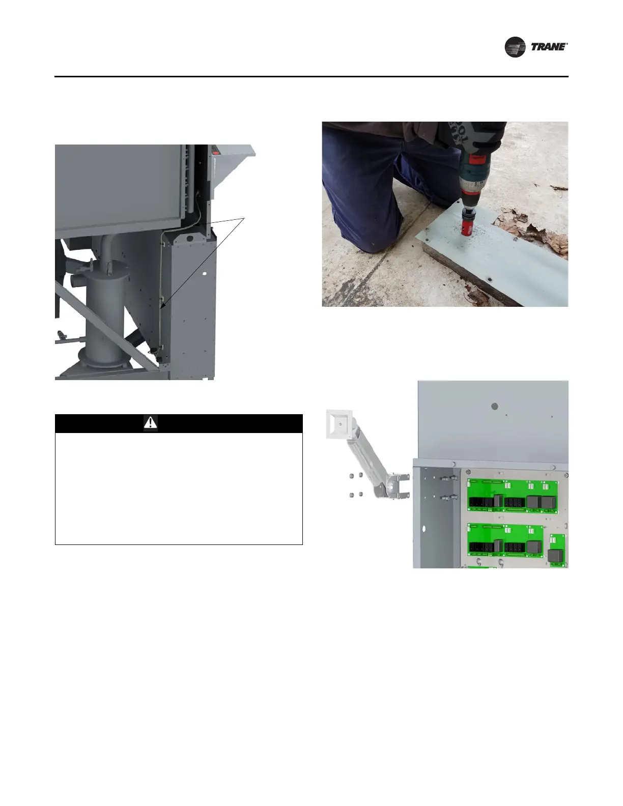
11. Secure cable with the adhesive mounted zip ties
provided in the kit. See Figure 14, p. 15.
Figure 14. TD7 cable routing
Arm Mount Option
CAUTION
Display Arm Under Tension!
Failure to follow instructions below could result in
minor to moderate personal injury. The display arm is
spring-loaded! Do not unfasten the Tracer AdaptiView
display from the display arm for any reason without
first decreasing the arm tension to its lowest setting!
Failure to relieve the tension from the spring-loaded
arm before unfastening the display could result in the
arm forcefully snapping upwards unexpectedly, the
moment the weight of the display is removed from it!
1. On the side of the control panel carefully position the
a
rm mount hole template (Figure 55, p. 49) and mark
the 4 required holes.
Note: Make sure arm mount location will not interfere
with control panel
door.
2. Using a ‘Q’ (0.332”) bit, drill the holes.
3. Using a 1-1/4” hole saw or knockout punch, create a
ho
le in the upper side panel for wire routing. See
Figure 15.
Figure 15. Wire routing hole creation
4. Secure the arm to the control panel enclosure using
the 5/16 - 18 sealed hex cap screws and lock nuts. See
Figure 16.
Figure 16. Arm installation
5. Securely fasten the Tracer
®
AdaptiView™ display to
the mounting plate on the end of the display arm with
the hardware provided. See Figure 17, p. 16
 Loading...


