Universal input troubleshooting
CNT-SVN01C-EN 91
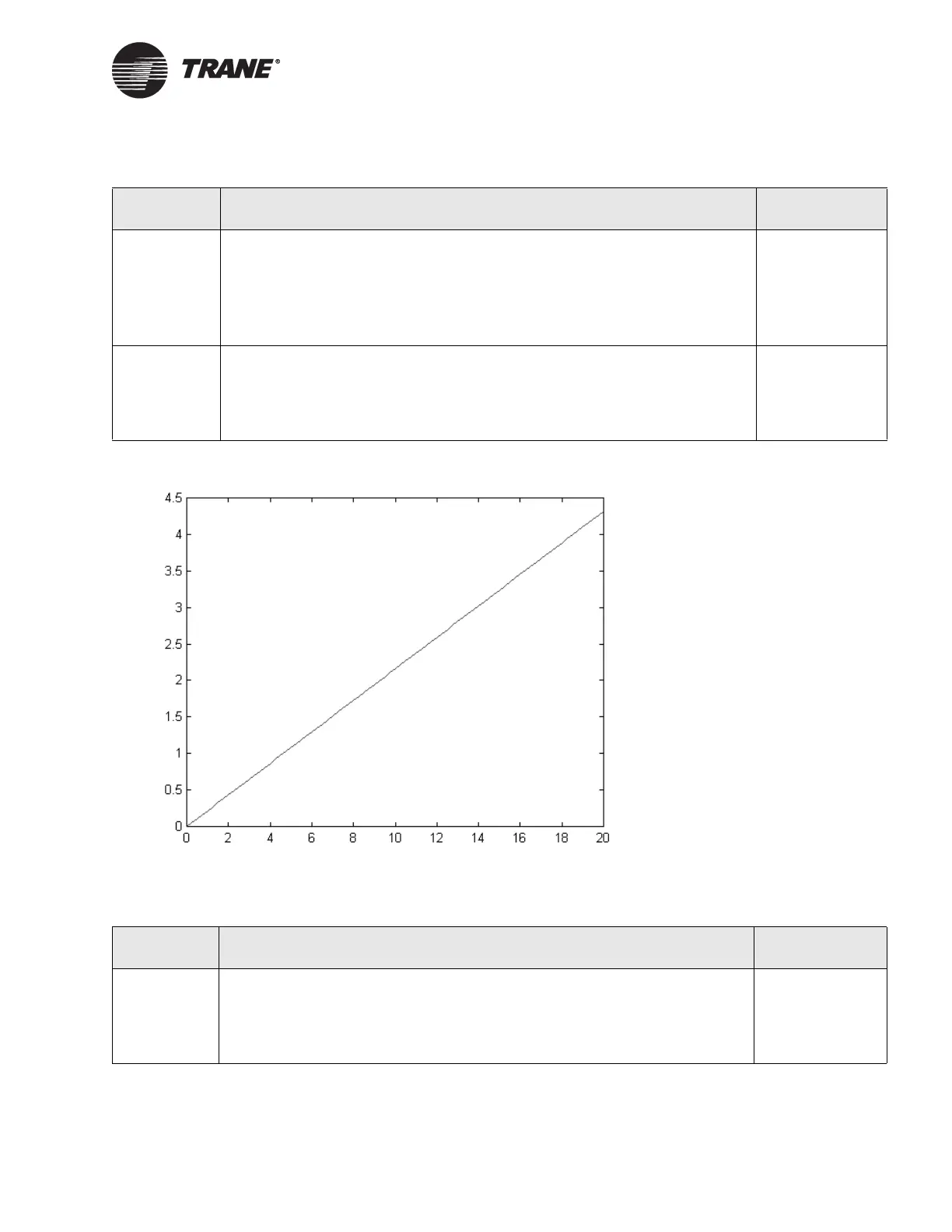
Figure 54. Voltage measured across terminals vs. input current
Table 28. Universal input troubleshooting with a 0–20 mA input
Step number Action Probable cause
Step 1 Set the multi-meter to read dc voltage. Measure the voltage across the termi-
nals for the input you are troubleshooting. Verify the voltage you measured
falls on the curve shown in Figure 54 for the input current.
If you do not see the voltage appropriate for the mA reading, you have a sen-
sor wiring problem.
If you do see the correct voltage for the mA reading, proceed to the next step.
Sensor wiring
problem
Step 2 Disconnect the sensor wires from the input terminals. Set the multi-meter to
read dc voltage. Measure the voltage across the terminals for the input you are
troubleshooting.
The voltage should be 0.10–0.13 Vdc (see Table 30 on page 92). If you do not
see a reading in that range, the Tracer MP581 has a circuit board problem.
Circuit board
problem
Table 29. Universal input troubleshooting with a 0–10 Vdc input
Step number Action Probable cause
Step 1 Disconnect the sensor wires from the input terminals. Set the multi-meter to
read dc voltage. Measure the voltage across the terminals for the input you are
troubleshooting.
The voltage should be 3.1–3.8 Vdc (see Table 30 on page 92). If you do not see
a reading in that range, the Tracer MP581 has a circuit board problem.
Circuit board
problem
Current (mA)
Measured voltage (Vdc)

 Loading...


