Wiring Comm5 to the Tracer MP581
CNT-SVN01C-EN 49
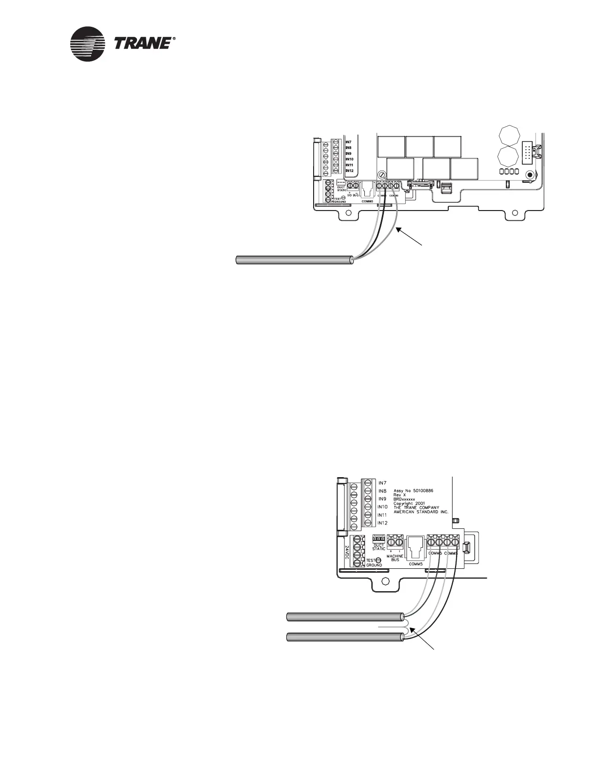
Figure 29. Grounding on the main circuit board
2. At the next Tracer MP581 (or other Comm5 controller) on the link:
• Connect the white wires to the first and third Comm5 screw ter-
minals as shown in Figure 30 on page 49.
• Connect the black wires to the second and fourth Comm5 screw
terminals.
• Splice together the bare shield wires and tape them.
3. At the last controller on the Comm5 link:
• Connect the white wire to the first Comm5 screw terminal.
• Connect the black wire to the second Comm5 screw terminal.
• Cut back and tape the shield wire to prevent grounding.
• Place a 100 Ω termination resistor across the Comm5 screw
terminals.
Figure 30. Connecting Comm5 wires at the Tracer MP581
Shield wire
Splice shield wires
and tape back

 Loading...


