14 BAS-SVX50F-EN
Installing the Tracer TD7 Display
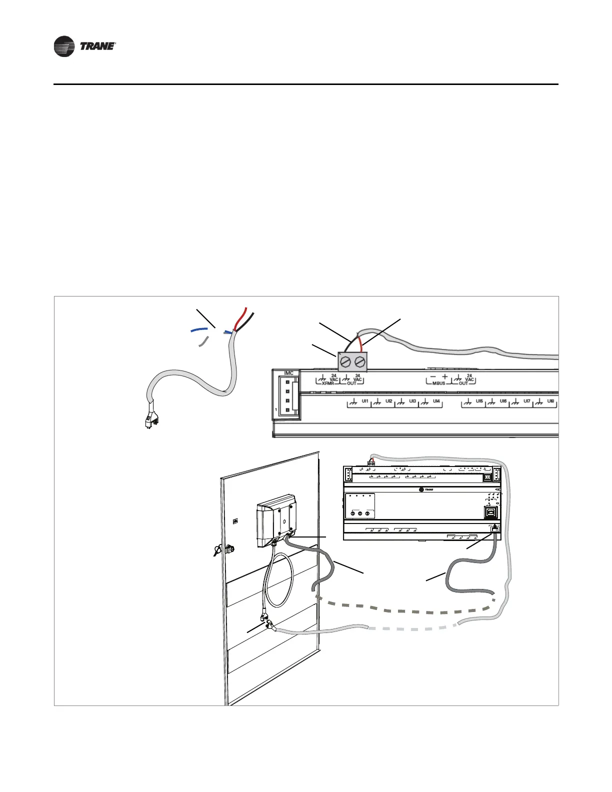
7. Snip off the blue and gray wires from the power cable with female connector
(PN: X19051625020)
4so only the red and black wires remain.
8. Place one of the supplied terminal
blocks 5onto an available 24 VAC terminal connection on
the UC600.
9. Insert the red wire
6through the 24 VAC connection, and the black wire 7through the ground
connection on the terminal block that was installed on the UC600. Tighten the terminal block
screws with a 1/8 in. (3 mm) slotted screw driver.
10. Connect the Ethernet cable
8to the Ethernet port 9on the TD7 display.
11. Route the Ethernet cable to the display port
0on the UC600.
12. Connect the ends
-of the two power cables together.
13. Reconnect the 24 VAC power to the UC600, remove lockout/tago
ut, and apply power to the
circuit.
Figure 3. Installing communication wiring
A
O
6
UI
14
A
O
5
UI
13
A
O
4
UI
12
A
O
3
UI
11
A
O
2
UI
10
A
O
1
UI
9
B
O
4
B
O
3
B
O
2
B
O
1
RELAYS
0
.
5
A MAX
IM
C
1
IM
C
P
1
UI
8
UI
7
UI
6
UI
5
UI
4
UI
3
UI
2
UI
1
IMC
+
24
VDC
LINK
OUT
+
24
VDC
+
24
VDC
OUT
24
VAC
MBUS
OUT
24
VAC
XFMR
24
VAC
SERVICE TOOL
SERVI
C
E
LINK
ACT
IM
C
MBUSLINK
RX
TX
U
C
600
ADDRESS
0
1
2
3
4
5
6
7
8
9
x1
0
1
2
3
4
5
6
7
8
9
x10
0
1
2
3
4
5
6
7
8
9
x100
B
O
4
B
O
3
B
O
2
B
O
1

 Loading...


