110 RT-SVX34C-EN
Startup
WARNING
Hazardous Gases and Flammable Vapors!
Exposure to hazardous gases from fuel substances have been shown to cause cancer, birth
defects or other reproductive harm. Improper installation, adjustment, alteration, service or use
of this product could cause flammable mixtures. To avoid hazardous gases and flammable
vapors follow proper installation and set up of this product and all warnings as provided in this
manual. Failure to follow all instructions could result in death or serious injury.
WARNING
Hazardous Pressures!
When using dry nitrogen cylinders for pressurizing units for leak testing, always provide a
pressure regulator on the cylinder to prevent excessively high unit pressures. Never pressurize
unit above the maximum recommended unit test pressure as specified in applicable unit
literature. Failure to properly regulate pressure could result in a violent explosion, which could
result in death or serious injury or equipment or property-only-damage.
Turn the main gas supply to the unit "On" and check the gas pressure at the unit's gas train. Refer
to the "Field Installed Gas Piping" section for the proper gas supply pressure and Figure 33, p. 52
for the location of the gas pressure taps.
Close the main power disconnect switch and start the first stage heating Test again. Wait
approximately 60 seconds for the heater to switch to low fire and check the manifold gas pressure.
The manifold pressure for a two stage burner must be set at negative 0.2" w.c., +/- 0.05" w.c. The
manifold pressure on a modulating burner should be set at a positive 0.5" w.c., +/-0.05" w.c. For
modulating burners, expect to see the manifold pressure reading fluctuate while the burner is
operating, but it should never read negative.
CAUTION
Hot Surfaces!
Surface temperatures may exceed 300°F (150°C) on flue and heat exchanger components.
Contact of bare skin on hot surfaces could result in minor to severe burns.
Jump the test terminals momentarily to initiate second stage heat operation. The combustion
blower motor should go to high speed. The second stage of heat in units with modulating gas will
initiate the second heater bank to fire and both banks will operate at high fire. The manifold
pressures of the two heater banks in a high heat modulating unit will be different. The pressure
setting of the two stage burner will be a negative 0.2" w.c., while the modulating burner will be a
positive 0.5" w.c.
Note: When firing a modulating unit for the first time, a "humming", or resonance sound may be
heard. This is an operational sound made by the burner screen as it burns in. This sound
is not a concern unless it persists longer than the first few times the unit is fired.
Electric Heat Units
Start the service test and check the amperage draw for each heating stage. Refer to the heater
electrical data in Table 11, p. 35 for the full load amps of a specific heater size.
Once the operation of the heaters have been checked, open the main power disconnect switch or
the unit mounted disconnect switch to shut the unit "Off" and to reset the RTRM.
This concludes the setup and testing for the major components and controls within the unit. Follow
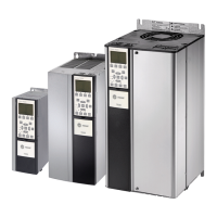
the Test guide in Table 28, p. 74 and Table 29, p. 74 to verify that the optional IGVs, VFD, economizer
actuator, minimum ventilation controls are functioning.

 Loading...


