RT-SVX34C-EN 145
Diagnostics
(CFS) Clogged Filter
Switch
This input is for "indication only
and does not effect the normal
operation of the unit.
"Normal operation = 0 VAC
measured between terminals
J5-1 and Ground.
SERVICE LED ON 2-30 VDC
present at RTRM J6-6 and J6-
10
(FFS) Supply Fan
Proving Switch
Unit will not operate in any
mode.
0.5" W.C. Normally Open
Service Failure Output at RTRM
J6-6 to J6-10 "SERVICE" LED
blinks at ZSM
(SPT) Static Pressure
Tran sdu ce r VAV
IGV will not open
0.25 - 4 VDC between J8 and J9
on VAV
Heat and Cool Failure Output at
RTRM J6-7 to J6-6 & RTRM J6-
8 to J6-6 "HEAT" and "COOL"
LED's
blink at ZSM
*NONE* = No LED indication
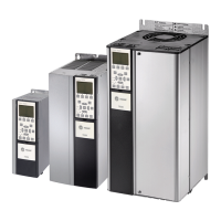
Table 79. Supply and Exhaust Fan VFD Programming Parameters for Model TR-1
Menu Parameter Description Setting Description
Load & Motor
102 Motor Power
Set Based on Motor
Nameplate
Set only for applications using 3hp Hi-
Efficiency motors. Set to 2.2 kW.
103 Motor Voltage
Set Based on Motor
Nameplate
Set only for 200/230v 60hz & 380/415
50hz applications
105 Motor Current
Set Based on Motor
Nameplate
Sets the motor FLA
106 Motor RPM
Set Based on Motor
Nameplate
Sets the motor RPM
Reference & Limits 215 Current Limit 1 x Rated Current Limits the maximum current to motor
Table 80. Supply and Exhaust Fan VFD Programming Parameters for Model TR-200
Menu Parameter Description Setting Description
Load & Motor
1-21 Motor Power
Set Based on Motor
Nameplate
Set only for applications using 3hp Hi-
Efficiency motors. Set to 2.2 kW/3 hp.
1-22 Motor Voltage
Set Based on Motor
Nameplate
Set only for 200/230v 60hz & 380/415
50hz applications
1-24 Motor Current
Set Based on Motor
Nameplate
Sets the motor FLA
1-25 Motor RPM
Set Based on Motor
Nameplate
Sets the motor RPM
Limits and Warnings 4-18 Current Limit 100% Rated Current Limits the maximum current to motor
Table 78. Component Failure Mode
COMPONENT FAILURE RESPONSE NORMAL RANGE DIAGNOSTIC

 Loading...


