41
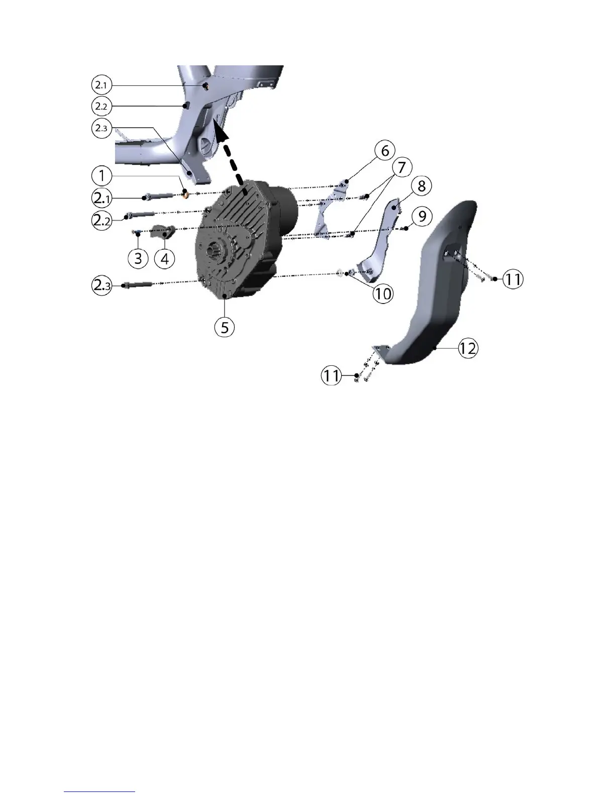
6.8.2 Drive unit mounting - technical drawing
Mounting parts of the drive unit
1. Additional bushing, L=5mm (!)
2. Bolts drive unit.
(Pos. 2.1 and 2.2: M8x60, 10,9
cylinder head, pos. 2.3: M8x60,
10.9, hex. head, from Bosch kit)
3. Bolt chain guide (M5x18, A2, 1x)
4. Chain guide
5. Drive unit
6. Motor plate
7. Bolts motor plate (M5x16, 10.9, A2, 2x)
8. Cover of electric connections drive unit
9. Screw of cover (M4x10, A2, 1x)
10. Washer and nut of 3rd drive unit bolt (M8, A2, 1x, Bosch kit)
11. Bolts and washers motor armor (M5x14, A2, 4x)
12. Motor armor





 To Next Page