Do you have a question about the Triacta Gateway and is the answer not in the manual?
Compliance statement for FCC Part 15 regulations.
Compliance statement for Industry Canada emission standards.
Outlines the guide's focus on mechanical and electrical installation.
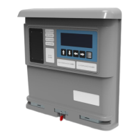
Details the capabilities and features of the Meter Head unit.
Describes the connection points and functionality of the Meter Base unit.
Explains the function of the Voltage Module and its inputs.
Steps for determining system requirements and site readiness.
Requirements for site power and lighting for installation.
Steps for physically mounting the Meter Base unit.
Procedure for installing CT/Pulse Wiring Modules into the Meter Base.
Guidance on installing disconnect devices for voltage inputs.
Instructions for wiring control and sense voltages.
Instructions for connecting the Ethernet cable for network communication.
Steps for installing the protective cover onto the meter base.
Procedure for replacing the fuse in the Voltage Module.
Classification of current transformers by output and appearance.
Proper alignment of CTs for accurate energy flow measurement.
Correctly connecting CT wires for accurate readings.
Determining the correct number and phasing of CTs for measurement.
Safe methods for shorting and terminating CTs.
Types and connection methods for CT/Pulse Wiring Modules.
Requirements for authorized access to the equipment.
Guidelines for inspecting and maintaining the equipment.
Policy on repairing or replacing individual components.
Explanation of graphical symbols used on the equipment.
| Brand | Triacta |
|---|---|
| Model | Gateway |
| Category | Measuring Instruments |
| Language | English |