© 2018 Triacta Power Solutions LP All Rights Reserved
from the CT match the X1/X2 leads from the convertor.
v. Connect the X1 lead (white) and X2 (black) leads from the 80mA side of the
converter to a CT cable or a CT / Pulse Wiring Module as described in the
previous two sections
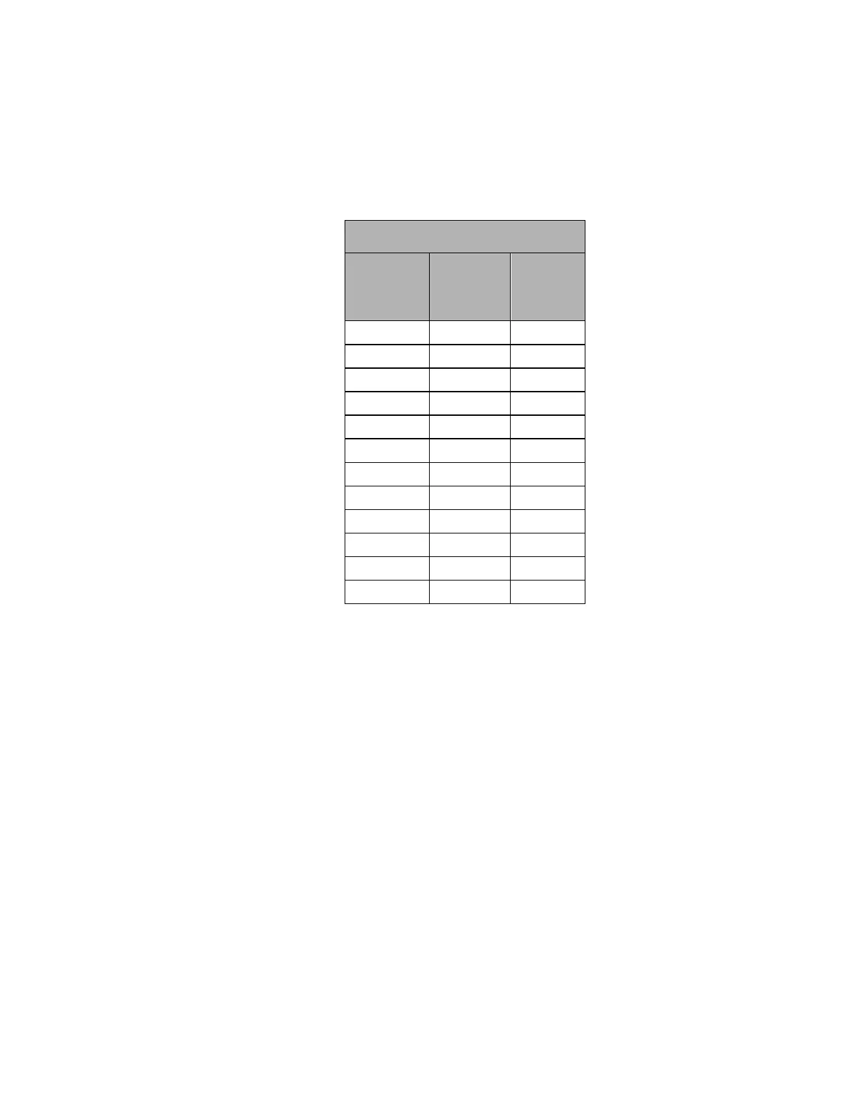
Table 3: CT / Pulse Wiring Module colour pair identification
CT / Pulse Input Termination Cable
Connect
CT X1 or
Pulse +
lead to:
Connect
CT X2 or
Pulse -
lead to:
Complete the installation record provided with each Triacta GATEWAY system to record
which CTs or pulse devices are connected to each input pair on each CT / Pulse Wiring
Module. See Figure 23 for an example.
Connect Pulse Inputs
Connect each external pulse output device to be monitored (gas, water, BTU meter, …) to a
separate pulse input pair (+/-) on any of the CT / Pulse Wiring Modules designated as a pulse
input module.
Each pulse input is compatible with both dry (reed) and solid-state Form A contacts.
When the pulsing device provides solid-state form A outputs, the negative terminal from the
source device must be connected to the negative (-) terminal of the Triacta GATEWAY pulse
in terminal block.
When the pulsing device provides dry contact (reed) pulse outputs the pulse input wire pairs
are not polarity-sensitive.
The maximum input pulse rate is 200 Hz (maximum), and the minimum input pulse width is
2.0 ms.