© 2018 Triacta Power Solutions LP All Rights Reserved
Triacta GATEWAY CT / Pulse Wiring Modules
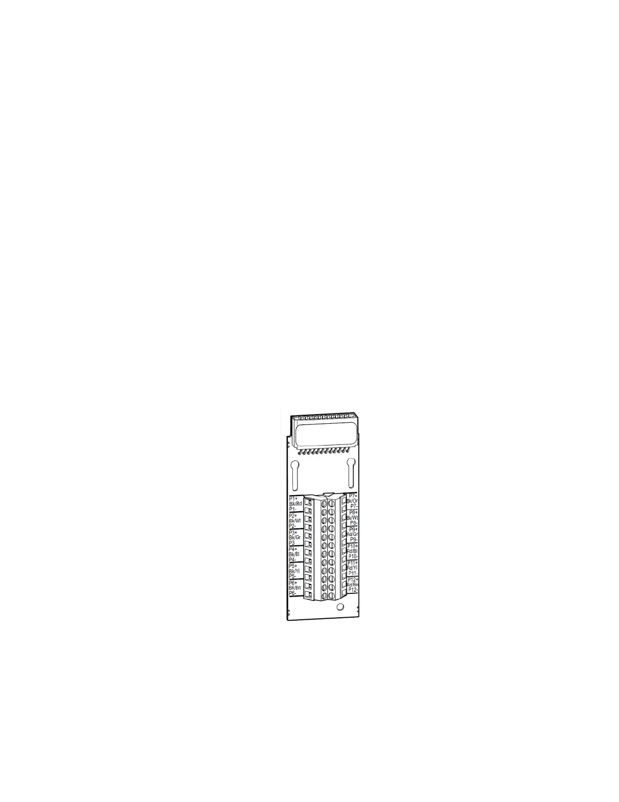
Current transformers and pulse output devices are connected to the Triacta GATEWAY via
specially designed self-shorting CT / Pulse Wiring Modules as shown below. The self-shorting
mechanism on each CT / Pulse Wiring Module is activated when the Triacta GATEWAY Meter
Head unit is not installed.
Each CT / Pulse Wiring Module supports 12 inputs pairs, numbered P1 to P12. The Triacta
GATEWAY Meter Base unit supports up to 4 CT / Pulse Wiring Modules for a total of 48 input
pairs. The number of inputs available of each type depends on the number of measurement
modules and CT / Pulse Wiring Modules installed in the meter.
The two inputs on each input pair are designated as + or -. If the CT / Pulse Wiring Module is
for CT connections, the X1 / X2 leads from each CT must respectively connect to the + / -
inputs. If the CT / Pulse Wiring Module is for pulse output devices, the + / - wires for each pair
connect as per the specific pulse output device type.
Each input pair on the CT / Pulse Wiring Module also has a colour pair designation that
matches on of the colour pairs available in an optional Triacta GATEWAY CT/Pulse
Termination Cable. Table 3 describes the termination cable wire pair colour scheme for each
input pair on the CT / Pulse Wiring Module.
The CT / Pulse Wiring Module is also available with a CT/Pulse Termination cable pre-wired
and over mold protected to the module as per the colour pair table.
Figure 5: CT / Pulse Wiring Module