© 2018 Triacta Power Solutions LP All Rights Reserved
Installation Instructions
This section provides information about activities that must be performed to install the Triacta
GATEWAY in a single-phase 2-wire, single-phase 3-wire (network), three-phase 4-wire or 3ph
3wire delta application. The installation procedures must be performed in the following order:
Mount the Meter Base Module
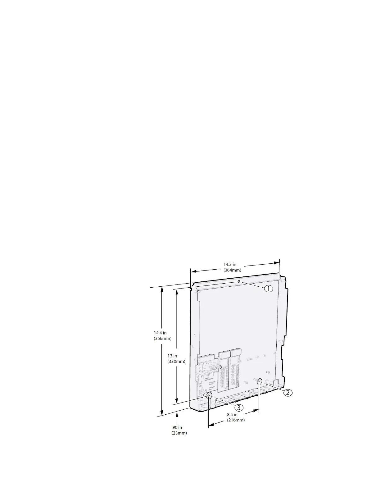
The Triacta GATEWAY can be mounted on a wall as a complete system with the Meter
Head unit pre-installed or as just the Meter Base unit with the Meter Head unit to be
installed later. Figure 7 shows the general mounting layout for a Meter Base unit on its
own. There are three mounting holes as shown which are all accessible with or without the
Meter Head unit installed.
1. Mount the Triacta GATEWAY adjacent to the main circuit breaker box using the 1-inch
(25-mm) #8 screws. If mounting the unit on a plasterboard surface, use cylinder plugs.
2. Remove the front cover from the meter by removing the three screws with a #2 Phillips
screwdriver. Retain the cover and screws for later re-installation.
3. Mount the Triacta GATEWAY on the wall and secure it by inserting a screw in each
mounting keyhole and tightening the screws.
4. Use the provided washer on the top mounting screw when installing the Triacta
GATEWAY onto soft surfaces. Install the washer between the Meter Base unit and the
soft surface.
Figure 7: Meter Base Unit and PT module Mounting Layout, Dimensions and
Clearances