© 2018 Triacta Power Solutions LP All Rights Reserved
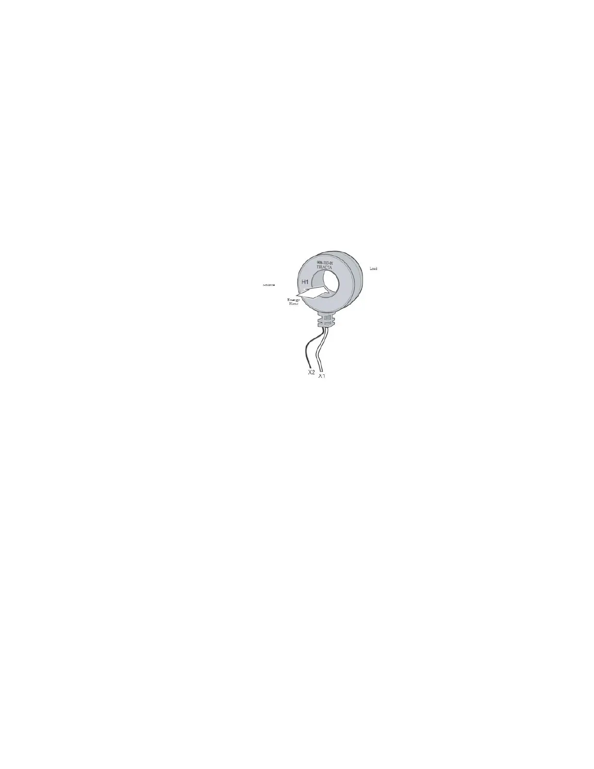
CT Orientation
When installing each CT, ensure that the orientation of the CT matches the direction
of the energy flow as indicated on each CT.
The direction of energy flow is identified by either;
1) a label - “This side towards source”,
2) an arrow - the arrow points away from the source, or
3) a stamp or label indicating which side is H1 - the H1 side faces towards
the source.
If the orientation is backward, the meter readings will be incorrect.
Figure 25: Triacta 100 or 80 mA current transformer
CT
Wiring polarity
Each CT has two output wires or posts. One output is X1 (positive) and the other output is X2
(neutral). The X1 output is normally labeled directly on the CT. It may be explicitly identified
as X1, or it may be identified with a dot. If there is no X1 marking, refer to the CT
manufacturer’s documentation to determine the proper polarity.
The X1/X2 outputs from each CT for each circuit must be connected to the X1/X2 inputs of
each corresponding CT input connection on the appropriate Triacta GATEWAY CT input
module.
When installing CTs in a panel, ensure that all CT wiring is labeled with the proper
X1/X2 designations, or that it follows a standard X1/X2 colour pair mapping. If the
CT wiring polarity is incorrect, the meter readings will be incorrect.
CT Phasing
Depending on the number of voltage phases and the number of wires connected to each
circuit being measured, a minimum of one, two or three CTs are required for each meter point
to correctly measure energy usage by the circuit.