© 2018 Triacta Power Solutions LP All Rights Reserved
The recommended wiring for pulse input pairs is 22 AWG shielded twisted pair wires for distances
up to 300 ft (100 m). Use larger gauge wire for larger distances up to 600 ft (200 m).
For each external pulse generating device, document the Wiring Module number and the wire pair
it is connected to, and the units per pulse output of the device.
Connect the Ethernet Cable
Connect the Triacta GATEWAY to a 10/100BaseT 802.3-2002 compliant IP network or
device by connecting a CAT5 Ethernet cable to the RJ45 Ethernet port on the Meter Head
unit. The Ethernet port enables TR3/TR5 data reporting and BAS Modbus IP or (future)
BACnet TCP/IP services to the Triacta GATEWAY device.
Route the Ethernet cable through one of the punch-outs in the bottom of the Meter Base.
There are two LEDS on the RJ45 jack which will indicate the status of the Ethernet
connection as shown in the following table:
Table 4: Ethernet Port LED Indicator Status
Connection State:
On – An active device has been detected
Off – No active device is connected.
Activity indicator:
Flashing On – Data activity detected on the interface
Off – No network activity detected.
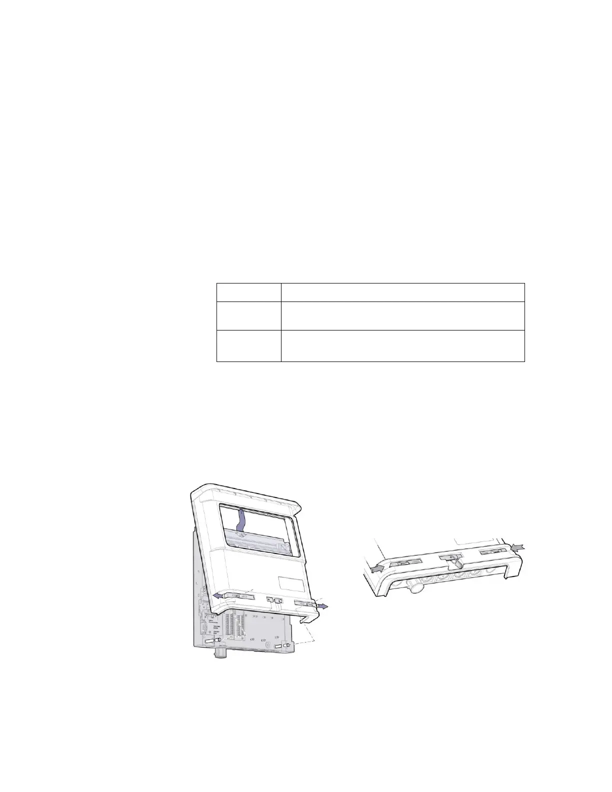
Install the Cover
The cover is installed from the top by holding it at a shallow angle and dragging down until the
inside of the drip cover catches the flange at the top of the Meter Base.
Figure 22: Installing the cover