32
External Wiring
SECTION VIII- External Wiring
Installation Compliance
All field wiring made during installation must
comply with:
- National Electrical Code NFPA 70 and any
other national, state, provincial or local
codes or requirements.
- In Canada, CSA C22.1 Canadian Electrical
Code Part 1, and any other local codes.
ELECTRICAL SHOCK HAZARD.
Before making any electrical connec-
tions to the PRESTIGE, disconnect elec-
trical power supply at the service panel.
Failure to comply can cause severe per-
sonal injury or death.
The line voltage terminals are located on
the right set of terminals 23 through 40.
The low voltage terminals are located on
the left set of terminals 1 through 22.
Line Voltage Connections
1. Connect a dedicated 120 VAC/15A service
to the line voltage terminal strip on the
wiring panel below the PRESTIGE control
module, as shown in Fig. 19, page 31.
2. Route the incoming 120 VAC power wire
through the provided openings in the bot-
tom jacket panel.
3. The unit is provided with a service switch
located on the front panel, check local code
requirements for compliance.
If local electrical codes or conditions
require an additional service switch, the
installer must provide and install a fused
disconnect or 15 amp (minimum) service
switch.
Circulator Wiring
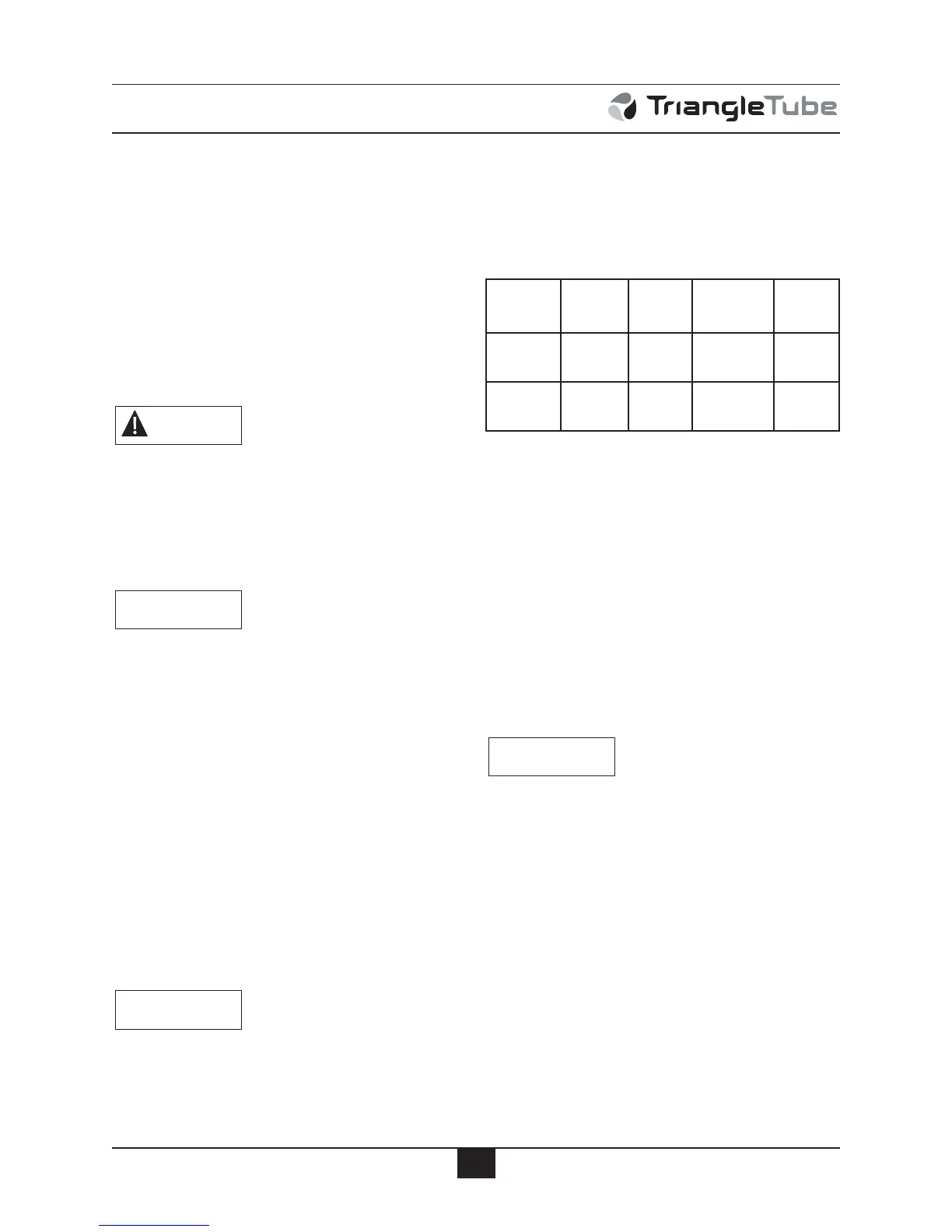
1. Reference Table 2 to determine the appro-
priate circulator connections required. The
circulator connections used will depend on
the systems piping layout.
Note1: Domestic Hot Water Priority can be dis-
abled in the Installer Menu which allows
the CH (1) and DHW circulators to oper-
ate at the same time. Consult the PRES-
TIGE TriMax Control Supplement for
more information.
Note2:The system circulator can also be
enabled during a DHW Call in the
Installer Menu. Consult the PRESTIGE
TriMax Control Supplement for more
information.
Each circulator is individually fused
with a 2.5A fuse located in the terminal
strip. The total combined amp draw of
the CH (1), DHW, and Auxiliary Boiler
Circulators must not exceed 4 amps at
any time for the Solo 60, 175, or 250.
The total combined amp draw of the CH
(1), DHW, and Auxiliary Boiler
Circulators must not exceed 3 amps at
any time for the Solo 399. Use an isola-
tion relay to lower the total combined
amp draw if exceeding these limits.
2. Connect the CH circulator to the line volt-
age terminal strip on the wiring panel
below the PRESTIGE control module, as
shown in Fig. 19 on page 31. The CH cir-
culator is enabled during a CH 1 or CH 2
NOTICE
WARNING
NOTICE
NOTICE
CH (1)
Pump
DHW
Pump
Auxillary
Boiler
Pump
System
Pump
CH 1 or
CH 2 Call
ON
OFF
(Note 1)
ON ON
DHW Call
OFF
(Note 1)
ON ON
OFF
(Note 2)
 Loading...


