63
Outdoor Reset Control
SECTION XII - Outdoor Reset
Control
The boiler setpoint for a space heating call can
be fixed or vary with the outdoor temperature.
The use of the outdoor reset function is recom-
mended to optimize boiler efficiency. The
default setting of the boiler is for a fixed space
heating setpoint. The outdoor reset function
can be enabled in Heating EZ Setup after the
outdoor sensor is connected to the boiler.
Mounting the Outdoor Sensor
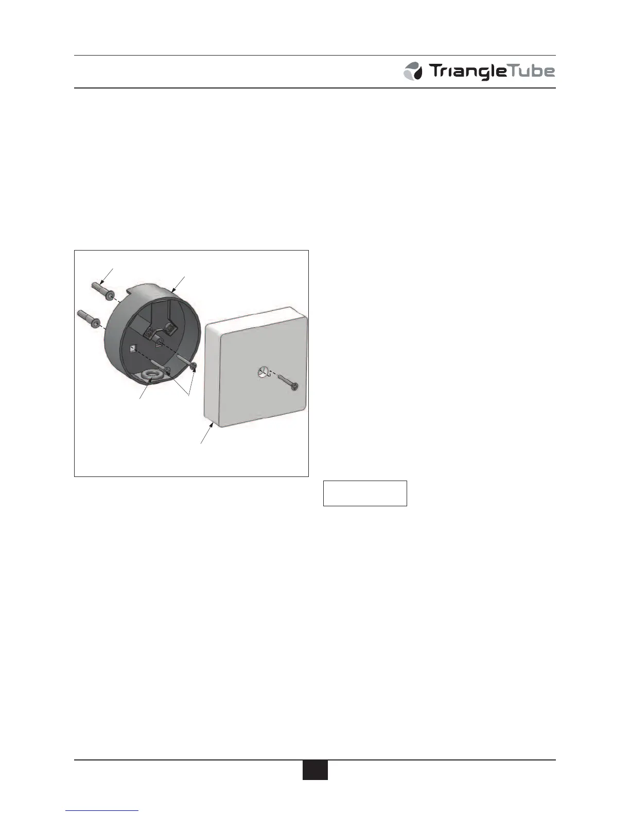
1. Remove the front cover and mounting
screws / anchors from the sensor enclosure.
2. When mounting the enclosure, the exterior
wall selected should represent the heat load
of the building. Typically a northern or
northeastern wall will suit most buildings.
A southern facing wall for those buildings,
which may have large glass walls or win-
dows on the southern face.
3. Ensure the sensor enclosure is shielded
from direct sunlight or the effects of heat or
cold from other sources (exhaust fans,
appliance vents...) to prevent false temper-
ature sensing.
4. Mount the sensor enclosure at an elevation
on the exterior wall to prevent accidental
damage or tampering.
5. Avoid mounting the enclosure in areas sub-
jected to excessive moisture.
6. Once an area on the exterior wall has been
determined, to affix the enclosure use the
enclosure as a template to mark the location
of the mounting screws.
7. Using a 3/16” drill bit, drill 2 pilot holes on
the marked locations.
8. Tap the enclosed plastic anchors into the
pilot holes. Use care not to damage the
anchors.
9. Mount the sensor enclosure using the
screws provided.
Wiring the Sensor
1. Cut a small slit in the seal gasket and route
18 AWG 2-wire cable or similar wire cable
through the seal gasket into the enclosure.
2. Route the sensor wire back to the PRES-
TIGE Solo boiler, ensuring the wires are
not run parallel to telephone or power
cables.
If the sensor wires are located in an area
with sources of potential electromagnetic
interference (EMI) the sensor wires
should be shielded or the wires should be
routed in a grounded metal conduit. If
using shielded cable, the shielding
should be connected to the common
ground of the unit.
5. Connect the sensor wires to the outdoor sen-
sor terminals on the low voltage terminal
strip located inside the boiler enclosure (see
boiler wiring diagram, Fig. 19 page 31).
NOTICE
Sensor Enclosure
(2) Plastic Anchors
Seal Gasket
Front Cover
(
2) Mounting
Screws
Fig. 32: Sensor Enclosure and Components
 Loading...


