UVM-1000
LIT-12013155
14
cfm / Percentage Selection
There is a DIP switch (when enabled) for each of the control
input and the feedback output. The individual DIP switch allows
the input or output voltage to be interpreted as cfm signal
or position signal. If the switch is set for cfm then the signal
represents what ever scaling the UVM is setup for cfms.
So if the cfm at 10 V is set to 1600, then an input voltage of 10 V
is a request for the valve to be at 1600 cfm, and a feedback out
of 10 V indicates the valve is doing 1600 cfm. If the DIP switch
is set to position, then 10 V is a request for the actuator to be
at 100%, and with the feedback Vo indicates the actuator is at
100%. There are separate switches for the input IN signal and
the output Vo signal.
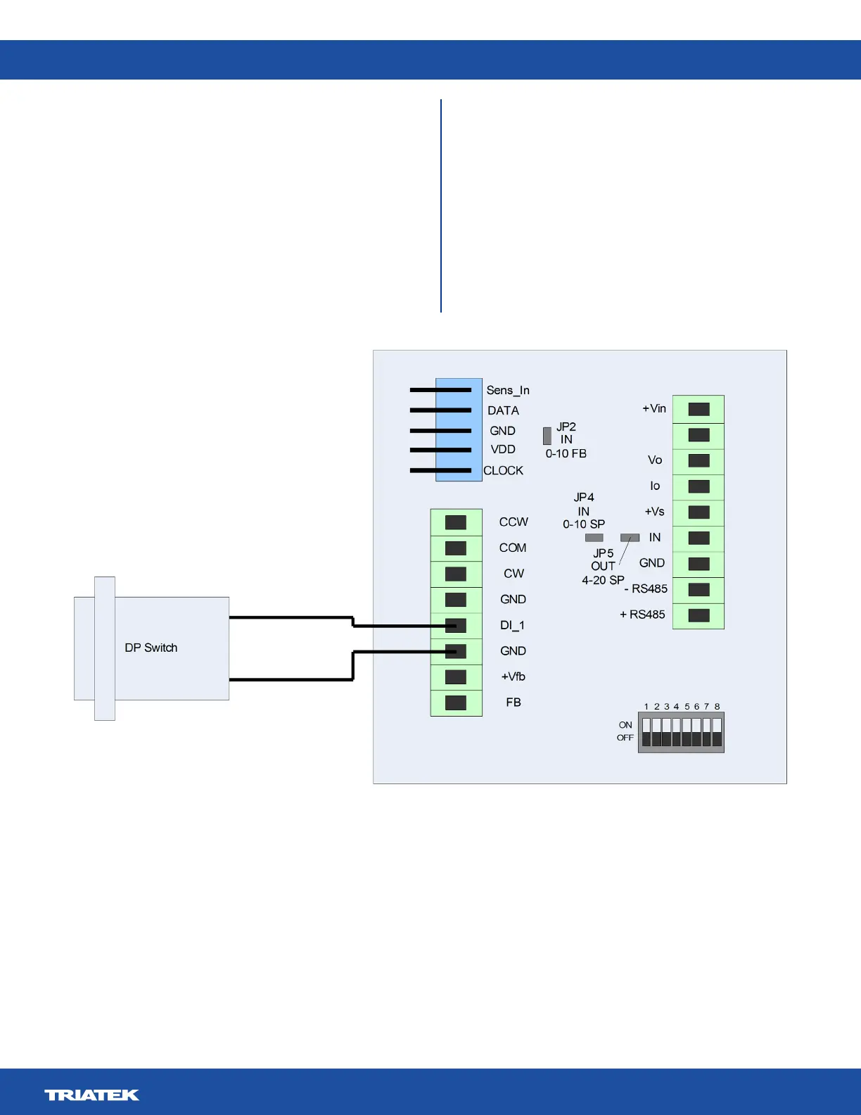
Valve Flow Integrity (DP Switch)
If a DP switch is to be attached, it is done by connecting
voltage free NO or NC contacts between GND and DI. The
UVM has an internal 15K pull-up to the internal 3.3 V rail. This
input is protected to 15 V for application of over-voltages. NO
or NC operating mode can be set in the UVM via the UVM
Conguration Tool.
- Vin
Figure 10. DP Switch Connections
 Loading...