UVM-1000
LIT-12013155
8
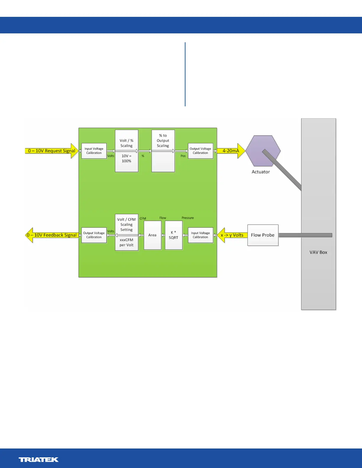
Figure 4. UVM use as a VAV Interface
The UVM can also be made to operate with a variable air volume
(VAV) box instead of a Venturi valve. In this case, instead of
providing the UVM with a cfm request signal, the input will
be interpreted as an actuator position signal where 0-10 V
represents a 0 -100% position signal.
This signal only provides positioning information for the VAV
box. The feedback sensor signal is replaced by the VAV box
ow probe pressure signal. This voltage signal is scaled and
converted to an internal pressure value.
The pressure value is then square-rooted and multiplied by a K
factor to obtain an internal velocity value. The velocity value is
multiplied by a duct area value to obtain an internal cfm value.
This cfm value is then scaled to the appropriate voltage, passed
to the Vo feedback voltage signal for use by the third party
controller. The scaling, K factor, and area can be set by the user
with the UVM Conguration Tool.
 Loading...