UVM-1000
LIT-12013155
9
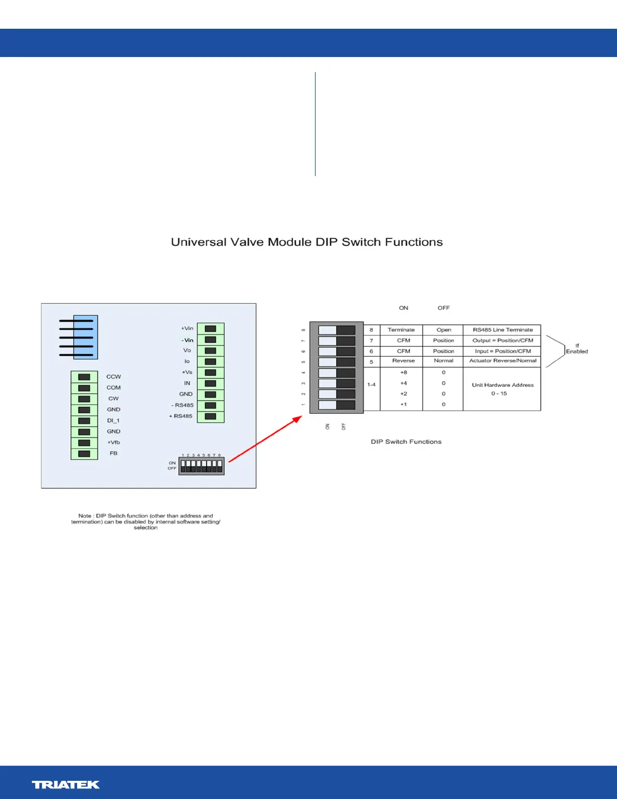
Figure 5. UVM Module DIP Switch Functions
Other than through the UVM Conguration Tool, the user does
not have access to any settings or operating modes of the UVM.
The exception is that the input and output signal modes and the
normal/reverse operation can be set via the DIP switches if that
functionality is enabled in the UVM.
The inputs and outputs can be set to be interpreted as a
Percentage (0 – 10 V = 0 – 100%) control or feedback signal, or
as a cfm ( 0 – 10 V = 0 – xxxx cfm ) control or feedback signal.
DIP switches 6 and 7 are used for this function. DIP switch 5 is
Normal Reverse Selection.
The UVM can communicate with the UVM Conguration Tool. To
this end, the UVM can reside at one of 16 hardware addresses.
These addresses are set via DIP switches 1, 2, 3, and 4. Via
the UVM Conguration Tool, the UVM is able to have up to an
additional 16 software addresses set for communications use.
 Loading...