Do you have a question about the Triax TDX and is the answer not in the manual?
Operating and storage conditions for the headend unit.
Input voltage and connection requirements for the headend.
Requirement for proper earthing of the headend unit.
Instructions for installing a single TDX headend unit.
How to mount the headend on a rack or wall.
Connecting power and earth cables to the headend unit.
Instructions for installing multiple TDX headend units.
Ventilation needs for multi-headend configurations.
How to connect headends directly using Link sockets.
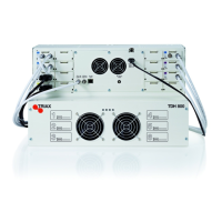
Connecting one main and one subunit directly.
Connecting one main and two subunits directly.
Power connection for headends.
How to connect headends via a network switch.
Using fiber optics for multi-headend connections over distances.
Procedure to reset the unit's IP address to factory default.
Lists and describes different types of input modules available.
Step-by-step guide for installing input modules into the headend.
Lists and describes different types of output modules available.
Step-by-step guide for installing output modules into the headend.
Explanation of headend and subunit status LEDs.
Meaning of System Status LEDs for headend and subunits.
Meaning of Tuner Status LEDs for input modules.
Meaning of Unit Link 1 LEDs for subunit connection status.
Meaning of Unit Link 2 LEDs for subunit connection status.
Introduction to the service tool for headend configuration.
Minimum requirements for using the service tool.
| Brand | Triax |
|---|---|
| Model | TDX |
| Category | Control Unit |
| Language | English |