Headend Overview
7
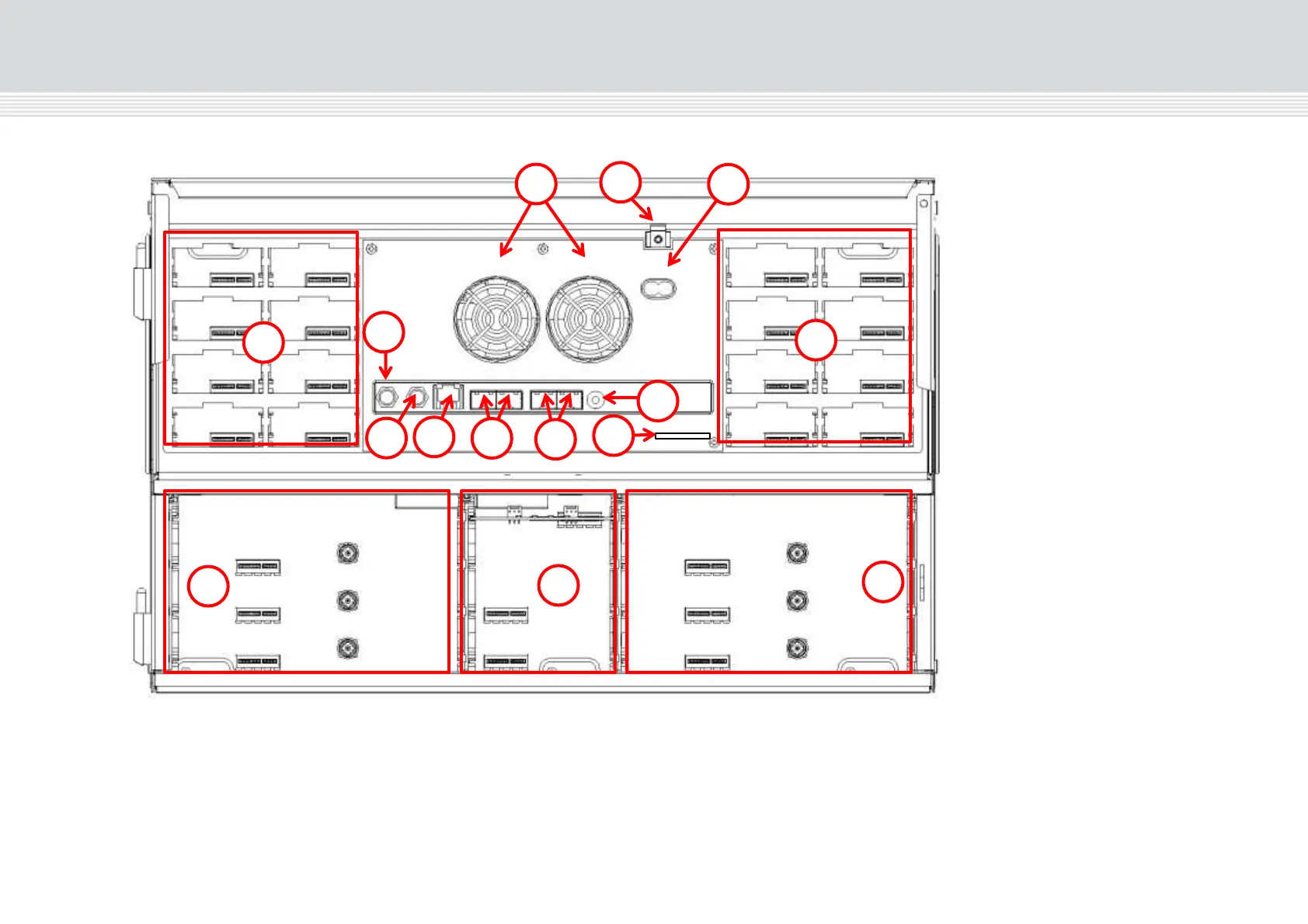
Interior
Input slots (16 in total)
RF output
Distributes the RF channels
from the output modules using
an F-connector.
Test point -20 dB
RF test point of output (-20 dB).
Configuration port
Ethernet configuration port for
setting up the headend unit.
AUX 1 & 2
Distributes services from IP
output modules.
Link 1 & 2
Connects the main unit with
subunits 1 and 2. Can also be
used in connection with IP input
and output.
ID switch
Switch for setting the ID of the
main unit and the two subunits.
Slot 1 & 2 for auxiliary boards
Auxiliary boards are used in connection with IP output modules.
Secure Digital (SD) card
Memory card for storage of the system configuration (behind panel).
Output slots (6 in total)