7D01-060en202008 Manual nanoFlu
UseCalibration
Malfunction &
Maintenance
Commis-
sioning
General
Information
FAQ Technical DataWarranty
Customer
Service
Contact
Keyword
Index
Accessories Introduction
nanoFlu // Introduction
2.3 Measurement Principle and Design
For optimal use of the sensor, you must know and understand the idea and theory that the sensor is based
on. The following is an overview of the measurement principle, the optical arrangement and the subsequent
calculation.
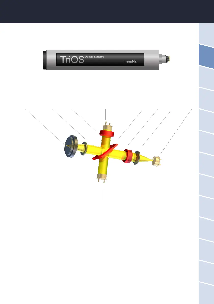
Essentially, the nanoFlu consists of four parts: a dened light source, a lens system, the optical path and a
detector with ambient light suppression. The arrangement of these parts is represented schematically in the
above illustration.
The light source consists of an LED with a dened wavelength depending on the version or parameter.
The excitation light beam is parallelized and a small part is reected by a beam splitter (short pass) onto a ref-
erence diode to compensate uctuations in the light source. A large part of the light is focused with a lens about
10 mm in front of the optical window. Fluorescent light is collected with the same lens and is reected again by
the beam splitter due to the higher wavelength. An interference lter in front of the photodiode for measuring
uorescence intensity prevents extraneous and scattered light from penetrating.
A special electronic circuit is used to eliminate ambient light.
Focal point Lens Filter Photodiode Beam splitter Filter Lens LED
Photodiode