24 D01-051en202111 Manual TriBox3
Advanced
Use
Malfunction &
Maintenance
Commis-
sioning
Introduction
General
Information
FAQTechnical Data Warranty
Customer
Service
Contact
Keyword
Index
AccessoriesUse
Use // TriBox3
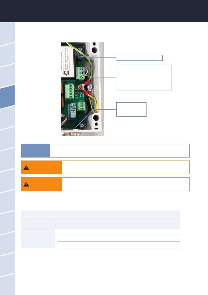
4. The gure below shows the position of the AC connection plug on the circuit board. Disconnect this plug
from the power supply.
Fuse F1 (see chapter 6.3.1)
Remove the plug from the socket,
open the tting and disconnect the
plug from the power supply line
Cable bushing
AC power supply
5. Remove the screws of the cable bushing and pull the power line out of the device.
CON1 connector
AC power supply
Pin Assignment
1 Protective conductor (PE)
2 Neutral conductor (N)
3 Phase (L)
6. Insert the new power line through the cable bushing into the device.
7. Connect the power line to the CON1 plug. The following table describes the contact assignment.
8. Reconnect the plug to the circuit board and tighten the nut of the cable bushing.
9. Check the grounding.
10. Close the housing of the TriBox3 and screw the cover back on. Attach the aluminium panels. The device
can now be put back into operation.
Always use wire end ferrules with exible conductors. Keep the exible conduc-
tors short. Make the protective conductor longer than the other conductors. The
large cable gland at the bottom right is designed for sheath diameters of 5-10 mm.
Use only one power cable whose insulation is sucient for the line voltage
and which has a ground wire (PE). The cross section of the cable must be
at least 0.75 mm
2
.
Before the power line is inserted into the TriBox3 or touches it, it is essen-
tial to make sure that the power to the TriBox3 is disconnected and cannot
be reconnected or switched on.
WARNING
WARNING
NOTICE