100
Maintenance and Adjustment
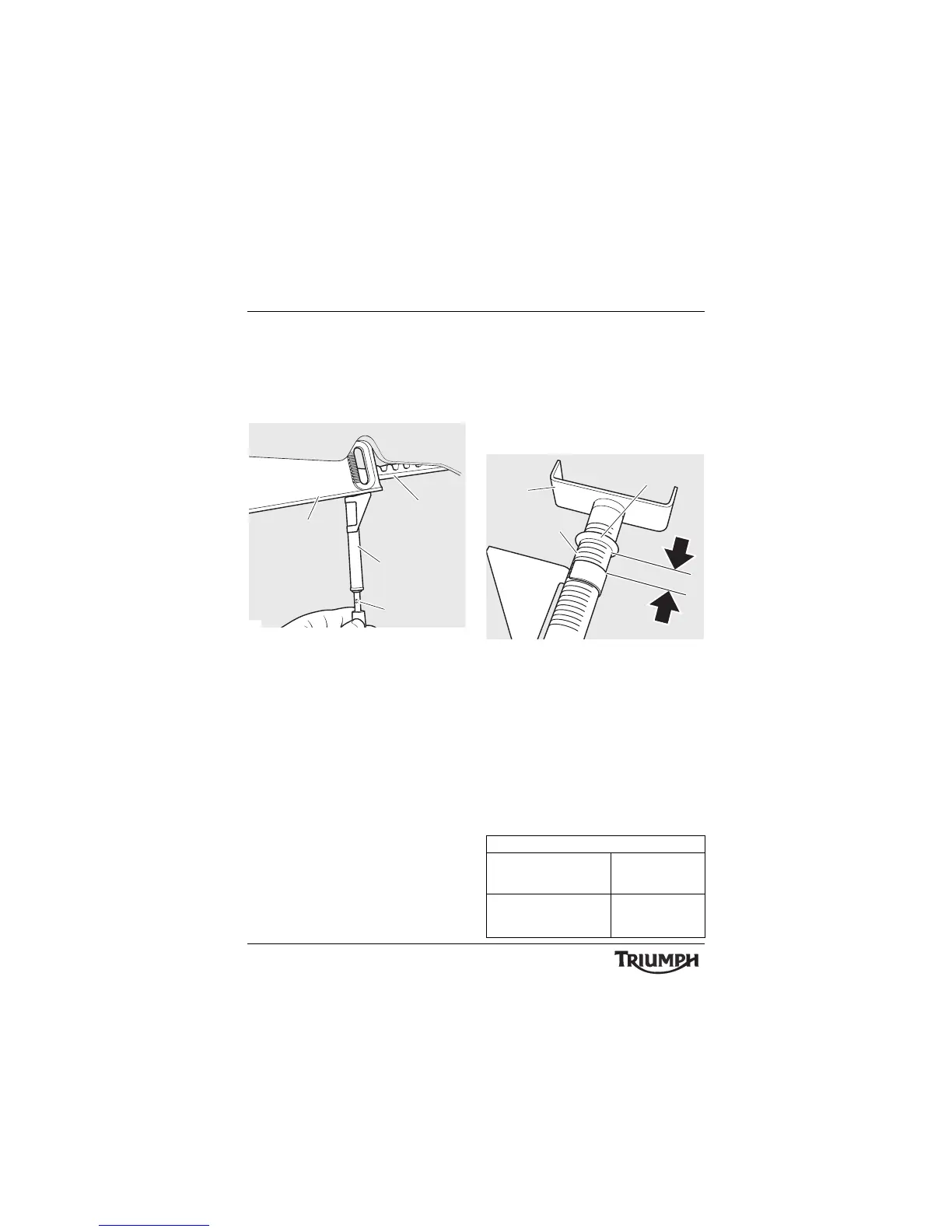
• Apply force to the belt tension
gauge in an upwards direction, until
the 4.5 kgf (10 lbf) mark on the load
scale is reached. The deflection slider
must remain stationary against the
belt cover while the force is applied.
1. Drive belt
2. Scale
3. Drive belt lower cover
4. Load scale
• Remove the tool, taking care not to
move the O-ring or deflection slider,
and read the belt deflection on the
scale on the tool. The belt deflection
is the gap between the top of
deflection slider and the lower edge
of the O-ring. The increments on the
scale are 0.020 in (0.5 mm) apart.
1. Belt deflection
2. Scale
3. Deflection slider
4. O-ring
• Repeat the measurement at several
points around the drive belt to locate
its tightest point. Always adjust drive
belt tension at the tightest point in
the drive belt.
If the drive belt deflection is outside the limits
given below, the drive belt must be adjusted
(see page 101 ).