EMISSION
AND
EVAPORATIVE LOSS CONTROL SYSTEMS
Cold
Starting
Fuel Injection
System
Components
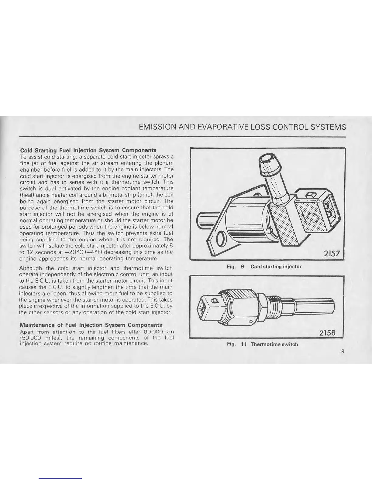
To
assist cold starting, a separate cold start injector sprays a
fine jet of fuel against the air stream entering the plenum
chamber before fuel
is
added
to
il
by
the main inJeclors. The
cold
start injector is energised from the engine starter motor
circuit and has
In
series with
it
a thermotime switch This
switch
is
dual activated
by
the engine coolant temperature
(heat) and a heater coil around a bi-metal strip (time), the coil
being again energised from the starter motor
CIrCUit.
The
purpose of the
thermotime
switch
is
to ensure that the cold
start Injector will not be energised when the engine is at
normal operating temperature or should the starter motor be
used for prolonged periods when the engine is below normal
operating termperature. Thus the switch prevents extra fuel
being supplied
to
the engine when it
is
not reqUired.
The
switch will Isolate the cold start injector after approximately 8
to 12 seconds at
-20°C
(_4°F)
decreasing this
lime
as the
engine approaches its normal operating temperature,
Although the
cold
start injector and thermotlme sWitch
operate independantly
of
the electronic control unit,
an
Input
to
the
E.C
U.
is
taken from the starter motor CIrCUlI. This input
causes the
E.C.U
to slightly lengthen the
time
that the main
injectors are ·open· thus
allOWing more fuel to be supplied to
the engine whenever the starter motor
IS
operated, This takes
place irrespective
of
the mlormation supplied to the
E.C.U
by
the other sensors or any operation
01
the cold start Injector
Maintenance
of
Fuel
Injection
System
Components
Apart from attention to the fuel filters alter
80.000
km
(50
000
milesL
the,
remaining components of the fuel
injection system reqUire no routme maintenance.
2157
Fig. 9 Cold
starting
injector
2158
Fig.
11
Thermotime
switch
9