EMISSION
AND
EVAPORATIVE LOSS CONTROL SYSTEMS
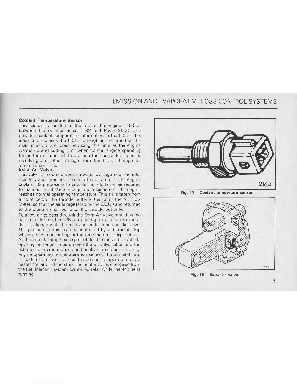
Coolant
Temperature
Sensor
This sensor is localed
al
the
top
of
the engme (TRl)
or
between the cylinder heads
(TRS
and Rover
3500)
and
provides
coolant
temperature mformatlon to the
ECU.
This
information causes the
ECU.
to lengthen the
time
that the
main injectors are 'open' redUCing this
lime
as
the engine
warms
up and
cutting
it
off when normal engine operating
temperture is reached. In practice the sensor
functions
by
modifying an
output
voltage from the E.CU through
an
'earth'
return
Circuit.
Extra Air
Valve
This valve is
mounted
above a water passage near the Inlet
manifold
and registers the same temperature
as
the engme
coolant. Its purpose
is
to provide the additional air required
to maintam a satisfactory engine Idle speed until the
engine
reaches
normal
operating temperature. This air
IS
taken from
a
point
before the throttle butterfly (but after the
Air
Flow
Meter.
so
that
the
air
is
registered by the E.CU,) and returned
10
the
plenum
chamber
after the throttle butterfly.
To
allow
air to pass through the Extra Air Valve. and thus
by-
pass the
throttle
butterfly. an opening in a rotatable metal
disc
is
aligned with the inlet and outlet tubes on the valve
The position
of
this
disc
is
controlled
by
a bi-metal striP
which
deflects according
10
the temperature
It
experiences
As the bi-metal strip heats up it rotates the metal
diSC
until its
opening no
longer
lines up
with
the air valve tubes and the
extra air source
is
reduced and finally terminated
as
normal
engine
operating
temperature
is
reached. The bi-metal strip
is
heated from
two
sources. the coolant temperature and a
heater coil around the strip. The heater
colliS
energised from
the fuel injection system
combined
relay
while
the engine
IS
running,
2164
Fig.
17
Coolant
tempertute
sensor
Fig.
18
Extra
air
valve
15