EMISSION AND
EVAPORATIVE
LOSS
CONTROL
SYSTEMS
"--:;:
=5:::::--_.",
"",""""
I
",'1M
: L
--;.~,,;"~.~
•
...,f\~
I
.,,"'"
I
.,"~
.
L
."""n
..
,.
.
.,
.................
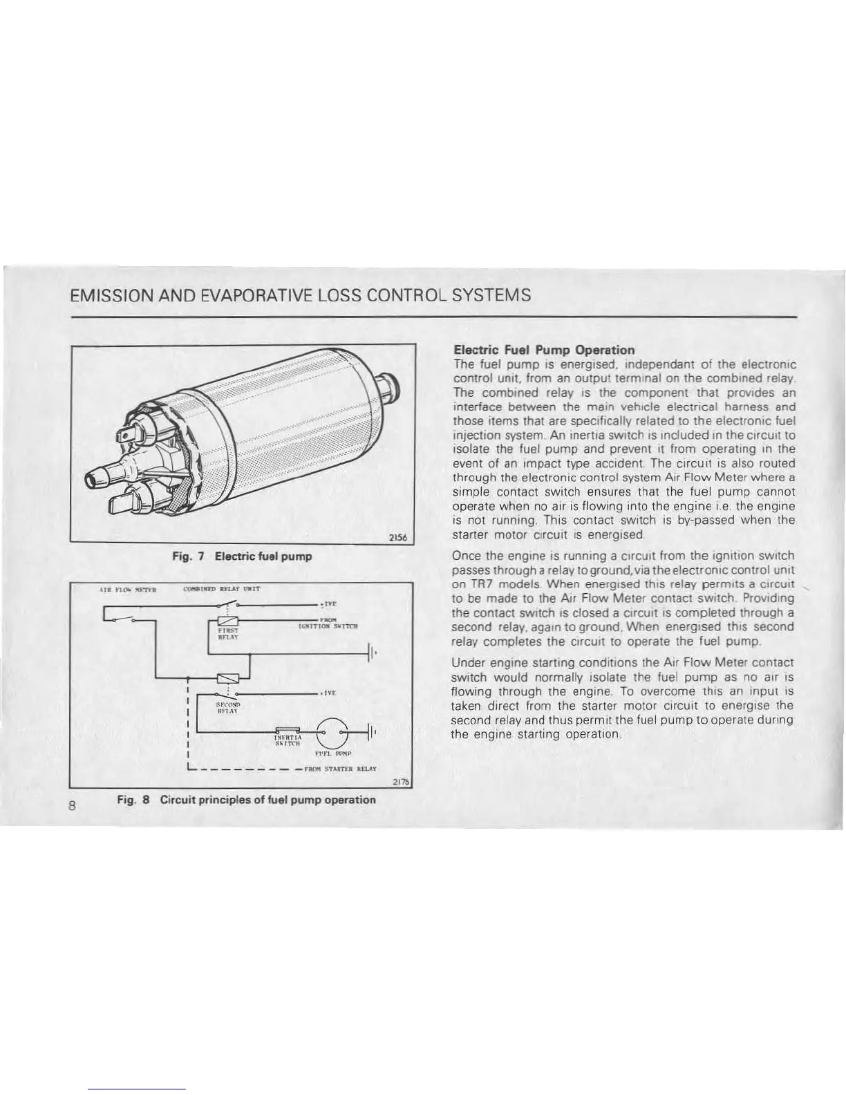
Fig. 7 Electric fuel
pump
..-,
......
n
.......
,,.
"--.------111·
""
Electric
Fuel
Pump
Operation
The
fuel
pump
IS
energIsed, .ndependant
of
the electrOniC
control
Unit, from an output terminal on the combined relay
The
combined relay
IS
the component that
prOVIdes
an
interface between the
main vehIcle electrical harness and
those ,tems that are spec,f,cally related to the electrOniC fuel
injectIOn system. An inertia
SWItch
.s
Included
In
the
CirCUit
to
Isolate the fuel pump and prevent
II
from operattng
In
the
event of an Impact type
accident
The
CIrCUit
is
also routed
through the electrOniC control system Air Flow Meter where a
simple contact
SWitch
ensures that the fuel
pump
cannot
operate when
no
air
IS
flOWing
mto the engine i,e the engine
is
no! running.
ThiS
contact
SWitch
IS
by-passed when the
starter motor
CirCUit
IS
energised
Once the
engine
IS
runnmg a
ClrCUlt
from the Ignl\lon
SWitch
passes through a relay ,aground,via the electroniC control Unit
on
TAl
models When energised th.s relay permIts a
CIrCUIt
to be made to the AIr Flow
Meter
contact
SWItch
ProvIding
the contact switch
IS
closed a
CirCUit
IS
completed through a
second relay,
again
to
ground. When energised thiS second
relay completes the
CirCUIt
to operate the fuel
pump
Under engme starting conditions the Air Flow Meter contact
switch would normally Isolate the fuel
pump
as no air
IS
flowing through the engine.
To
overcome thiS an Input
IS
taken direct from the starter motor
CirCUit
to
energise the
second relay and thus
permit the fuel pump
to
operate during
the engine starting operation
8
Fig. 8 Circuit
principles
of fuel
pump
operation